
 PCB Assembly
 Layer Buildup
 Online Tools
 PCB Design-Aid & Layout
 Mechanics
 SMD-Stencils
 Quality
 Drills & Throughplating
 Factory & Certificate
 PCB Assembly Factory Show
Certificate
PCB Assembly Factory Show
Certificate
Support Team
Feedback:
support@nextpcb.comFaraday's Laws
Michael Faraday first discovered the principles of electromagnetic induction (when a conductor intersects any magnetic field, then e.m.f generates in that particular conductor. This state of generation of e.m.f is known as electromagnetic induction) in 1831. Under this principle, Faraday devised the following laws;
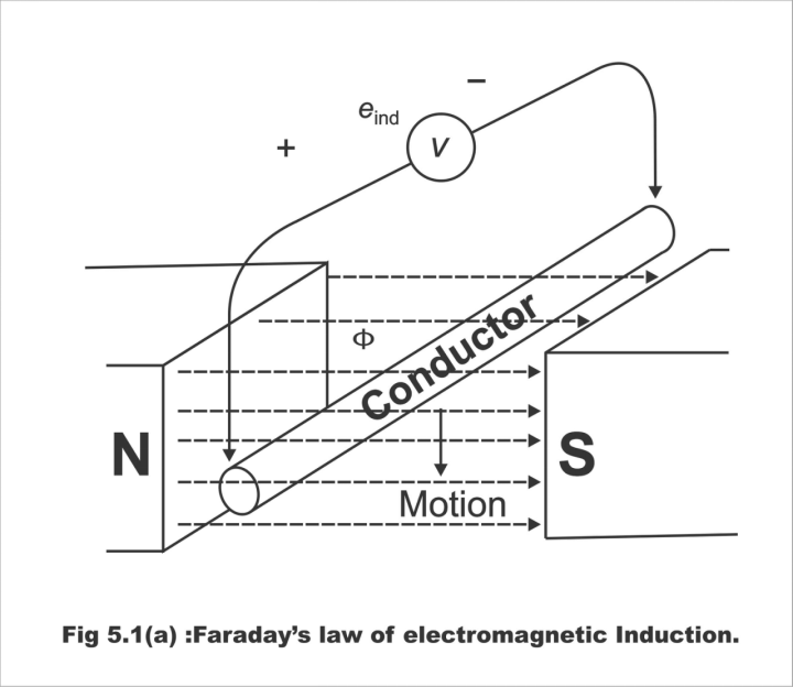
Fig. 5.1 (a) 0 Faraday’s law of electromagnetic induction
First Law
Whenever any conductor or coil intersects a magnetic field, e.m.f generates in it. In other words, whenever a magnetic flux is linked to a circuit, then a change occurs in flux. As a result of this change in flux, e.m.f is generated in the circuit.
Second Law
According to this rule, the quantity of induced e.m.f tends to be directly proportional to the rate of a change in the flux magnetic or flux linkage. That's the higher the change in flux, the higher will be the change in generated e.m.f. In other words, the larger the number of flux that a conductor or coil will intersect, the larger will the e.m.f going to be produced on it. i.e., d ф / dt
Faraday's law states that
Whenever the flux associated or linked with a circuit is changed, an e.m.f is induced in the circuit. This e.m.f lasts only when the change is taking place. The induced e.m.f varies as the rate of flux. Or the e.m.f induced in an electric circuit is proportional to the time rate of change of the flux of magnetic induction linked with the circuit. The magnitude of the induced e.m.f is directly proportional to the rate of change of current.
Remember, that the quantity of e.m.f generated in a situation where a coil is directly proportional to the number of turns (N) existing in the coil.
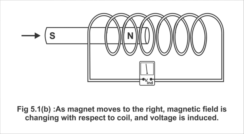
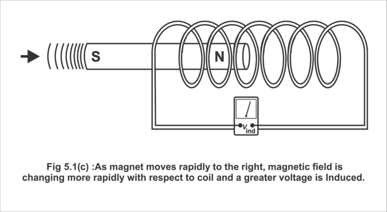
In Figure 5.1 (b), a bar magnet has been moved at a certain rate in the coil, thus, certain specific voltages are induced. In figure (c) magnet has been shown to move pretty hastily inside the coil, thus very large voltages are produced.
Fig. 5.1 (b); As the magnet moves to the right, the magnetic field is changed with respect to the coil, and a voltage is induced.
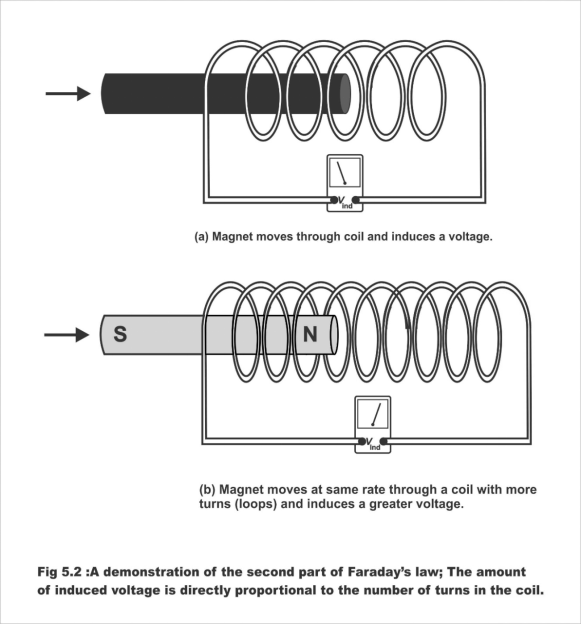
In Figure 5.2 (a), a magnet has been shown to be moved into a coil having a small number of turns. The voltages thus induced have also been illustrated. In Figure 9b), the magnet has been shown to be moved at a uniform speed in a coil having a large number of turns. A higher voltage results owning to a higher number of turns.
Fig. 5.1 ©; As the magnet moves more rapidly to the right, the magnetic field is charging more rapidly with respect to the coil and a greater voltage is induced.
A demonstration of the first part of Faraday's law; The amount of induced voltage is directly proportional to the rate of change of the magnetic field with respect to the coil.
Figure 5.2; A demonstration of the 2nd part of Faraday's law; The amount of induced voltage is directly proportional to the number of turns in the coil.
Explanation
Let us assume that a coil consists of N turns, and in time “t” second, a change occurs in the coil's flux from its initial value ф1 to the final value ф2. It should be remembered here that flux linkage means; the multiplication of the number of turns to the flux being linked, i.e.,
Initial flux linkages = N ф1
Final flux linkages = N ф2
Induced e.m.f, ie = N ф2 - N ф1/ t wb / s or volt
∴ Induced e.m.f, ie = N ф2 - N ф1 / t wb/ s or volt
Giving a differentiating form to the above equation;
e = d / dt (N ф) = N = d ф / dt volt
Here, the rate of change of flux is dф, and this flux changes in a minimum time dt. Normally, a negative sign is put along with right the side equation as has been mentioned above, which means that this induced e.m.f operates the current in that direction that it opposes the production mechanism, through which it generates the magnetic effect. i.e.,
e = -N dф / d t volt
Let us remember that in case of an equation, Faraday's law can be stated as below;
e = N (d ф / dt)
It has been proved from the above-mentioned formula that the voltages induced in a coil equal the product of the rate of change of flux (dф/ dt) and the number of turns (N).
Dynamically and Statically Induced E.M.F
In order to induce e.m.f, changes can be made in flux existing on any magnetic field in the following ways;
(1). Dynamically Induced E.M.F
If the magnetic field remains static, and the coil or conductor is turned into this field, the e.m.f which will thus be induced, is known as dynamically induced e.m.f. This principle is used in DC generators.
(2). Statically Induced E.M.F
If the conductor is retained static and the magnetic field is moved, or if it fluctuates, then the resulting e.m.f thus produced is called statically induced e.m.f. It should be remembered that for making variations or increase or decrease in flux, the current producing magnetic field, is either increased or decreased. In transformers, e.m.f are induced under this very principle.
There are further two types of a statically induced e.m.f;
(a). Mutually Induced e.m.f
(b). Self-Induced e.m.f
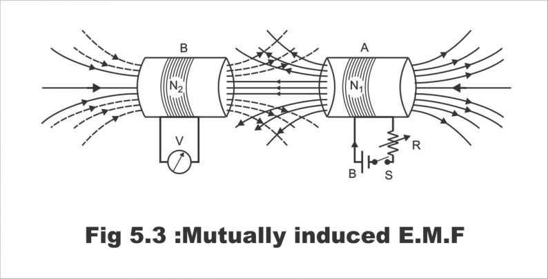
(a). Mutually Induced E.M.F
Let us assume that two coils A and B are lying close to each other, as has been demonstrated in Fig. 5.3. Coil A has been connected to a battery, a switch, and a variable resistance R. While, coil B has been linked to a sensitive volt meter. When the switch connected with coil B is closed, the flow of current starts from this coil as a result of the completion of the circuit. As a result, a magnetic field is generated around the coil, which partially gets linked with coil B. As soon as the coil current is varied through the resistance R linked with coil A, the flux linked to coil B also changes. As such, a mutually induced e.m.f is produced in coil B, the magnitude of which is determined according to Faraday's rule, whereas its direction is according to Lenz's rule.
Figure 5.3; Mutually induced e.m.f
Now, if according to Figure 5.4, the battery is connected to coil B and the volt meter is linked to coil A, then the situation changes. Now, changing the current in coil B will produce mutually induced e.m.f in coil A.
Figure 5.4; Mutually induced e.m.f
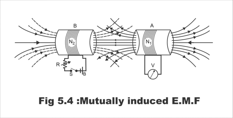
It has to be remembered that both coils A and B are static in their places, and no motion takes place in them at all. The variation in flux occurs solely as a result of changing the strength or value of the current. This e.m.f generated in one coil resulting from the impact of some other coil, is known as statically mutually induced e.m.f.
(2). Self-induced E.M.F
An e.m.f which is generated through linking a coil with its own flux, is called self-induced e.m.f. In other words, e.m.f which is produced in a coil as a result of the automatic disconnection of the magnetic field from its coil.
Figure; Self-induced E.M.F
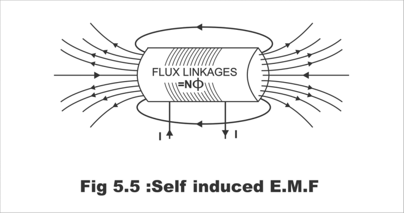
If the current flowing through the coil changes, then the flux of this coil linking with its own turns, will also change (i.e. flux strength will increase as a consequence of an increase in the current's magnitude, and flux will weaken as a result of a decline in current's value). This changing flux will induce e.m.f in the coil by cutting the coil's own turns, which is known as self-induced e.m.f. The direction of this induced e.m.f (which is determined by the Lenz law), is such that it opposes almost any such changes which are likely to occur in the flux, on the basis of which this flux is actually generated. Therefore, it is also known as counter or back e.m.f of self-induction.
Lenz's Law
According to this law;
(i). When an e.m.f is induced in a circuit, the current setup always opposes the motion, or change in current, which produces it.
(ii). An induced current will cause a current to flow in a close circuit in such a direction that its magnetic effect will oppose the change that produces it.
Through this law, which was started by Lenz in 1835, the direction of an induced current can also be determined.
(iii). When the current through a coil changes and an induced voltage is created as a result of the changing magnetic field, the direction of the induced voltage is such that it always opposes the change in current.
(iv). Lenz's law states that an induced effect is always such as to oppose the cause that produced it.
Explanation
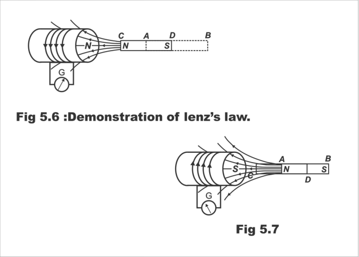
Lenz's law can be explained with the help of figures 5.6 and 5.7. In Fig 5.6, an insulated coil has been displayed, along terminals to which a sensitive galvanometer G has been linked. A static bar magnet is first placed near this coil at position AB. Some parts of the static magnet link with the flux coil, however, no motion is affected in the galvanometer's hand. Now if the bar magnet is brought suddenly or very swiftly to the position CD located closer to the coil, the galvanometer's hand will move with a jerk momentarily. Remember that this motion will continue, so long as the magnet remains active with respect to the coil, that's so long as relative motion between magnet and coil continues. As soon as the magnet's motion stops, the galvanometer's hand will also become static.
Now, if the magnet is repelled suddenly from the coil at position AB as shown in Figure 5.7, a motion will be created in the galvanometer's hand for a moment once again, and this motion will continue so long as the magnet remains active. As soon as the magnet becomes static, the galvanometer's hand will stop. It is worth reminding here that this motion of the needle/hand will be opposite to the direction of motion shown in Figure 5.6. That's if the magnet is brought closer to the coil, then a large flux links with the coil, and if the magnet is carried apart from the coil, then a reduction occurs in the rate of linking of flux with the coil.
Fig. 5.6; Demonstration of Lenz's law
Fig. 5.7
The movement of a galvanometer's hand/needle reflects e.m.f produced in the coil. There is only one reason for the creation of e.m.f, that is suddenly bringing the magnet closer to the coil, or removing it suddenly from the coil. Thus, it has been proved that the actual reason for this e.m.f is a change of the flux linkage with the coil and this e.m.f continues to generate only until the process of change in flux remains intact. Even if a powerful flux is static, it does not produce e.m.f in static conductors at all. It should be remembered that if the coil is moved back and forth keeping the bar magnet static, the same result will be achieved.
It can be inferred from the aforementioned discussion that when the N pole of the bar magnet is brought closer to the coil, e.m.f produces, as a result of which, current flows through the coil. If the magnet is viewed from the side, then this current can be seen moving in an anti-clockwise direction. Thus, the front part (face) of the coil, becomes the N pole. As such, the coil's N pole and magnet's N pole propel each other apart, and to overcome this repulsive force, mechanical energy is consumed. This mechanical energy converts into electrical energy, which is reflected in the coil.
When the magnet is pushed away from the coil, as has been shown in Fig 5.7, the current flows in a clockwise direction. Thus, the front part of the coil becomes a “S” pole. Therefore, the magnet has to be removed away opposite to the relative attraction between the magnet's N pole and the coil's S pole. To overcome this magnetism power, mechanical energy is required once again, which then converts into electrical energy.
It has thus been proved that induced current always flows in such a direction, that it prevents the relative movement by means of its magnetic field, owing to which it has been produced (Relative or mutual motion means bringing the magnet nearer or away from the coil)
To be continued:
Still, need help? Contact Us: support@nextpcb.com
Need a PCB or PCBA quote? Quote now
|
Dimensions: (mm) |
|
|
Quantity: (pcs) |
|
|
Layers: 2 |
Thickness: 1.6 mm |
|
|
|

 Printed Circuit Boards
 Surface

