
 PCB Assembly
 Layer Buildup
 Online Tools
 PCB Design-Aid & Layout
 Mechanics
 SMD-Stencils
 Quality
 Drills & Throughplating
 Factory & Certificate
 PCB Assembly Factory Show
Certificate
PCB Assembly Factory Show
Certificate
Support Team
Feedback:
support@nextpcb.comRaspberry Pi shook the embedded community in 2024 with the announcement of the new RP2350. Better in almost every way, the new 32-bit microcontroller opens up a plethora of new possibilities and improvements over its hugely popular predecessor, paving the road for similar if not greater success. Design resources are already circulating on the world wide web with many enthusiasts creating and sharing resources for KiCad. In addition to being accessible and easy to use, the open-source EDA software is the ideal choice for designing custom PCBs based on the new silicon.
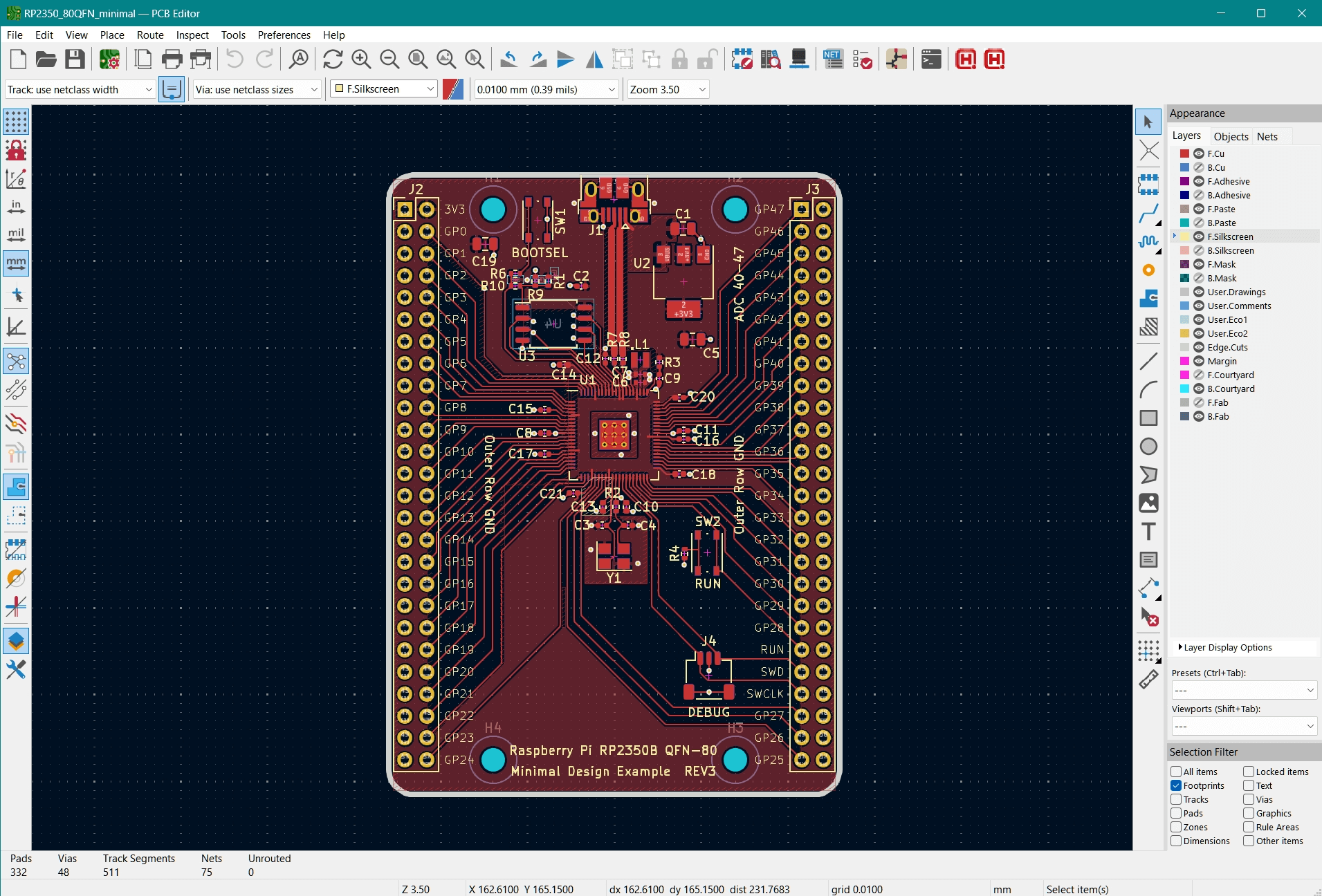
Minimal RP250B Reference Design in KiCad
In this article, we summarize key tips and resources for KiCad designers whether you are eager to design new designs using RP2350 or upgrade previous RP2040 designs to use the new silicon. NextPCB is also sponsoring RP2350 designs with free prototypes, covering PCBs and components - including the elusive chips, assembly and shipping.
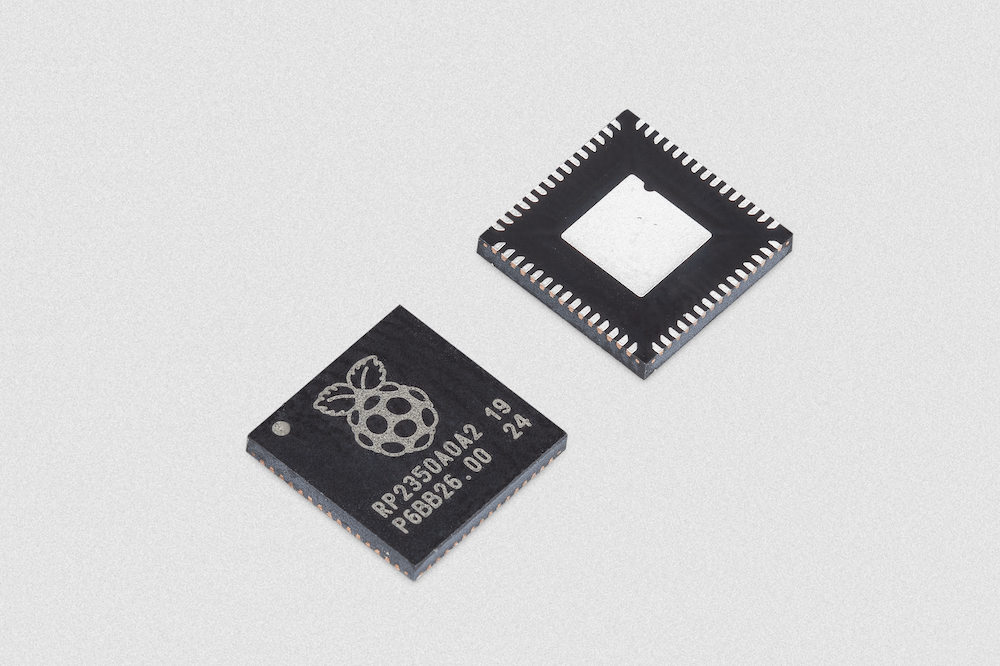
Introduced in August 2024 alongside the Raspberry Pi Pico 2, which is based on the new silicon, RP2350 is touted by the creators as "Just as good, but better", referencing its predecessor and Raspberry Pi's debut microcontroller, the RP2040.
The RP2350 improves on RP2040 with a higher clock speed from 133MHz to 150MHz, double the on-chip SRAM to 520kB and a set of unique features such as dual architectures, robust security features, lower power consumption and more configurations, including internal flash options.
| RP2040 | RP2350 | |
| CPU | Dual Cortex-M0+ @ 133MHz | Dual Cortex-M33 + FPU or Dual RISC-V Hazard3 @ 150MHz |
| RAM | 264KB SRAM | 520KB SRAM |
| Flash/Boot | XIP QSPI | XIP QSPI v2 with PSRAM support |
| PIO | 2 x PIO v1 blocks | 3 x PIO v2 blocks |
| GPIO | 30 pins | 30 or 48 pins depending on model |
| Peripherals | 2 x SPI, 2 x UART, 2 x I2C, ADC, PWM, USB 1.1 | 2 x SPI, 2 x UART, 2 x I2C, ADC, PWM, USB 1.1 |
| Low Power | ~100μA | ~57μA |
| Packages | 56-pin QFN (7 x 7) | 60-pin QFN (7 x 7) or 80-pin QFN (10 x 10) depending on model |
In addition to being more powerful, RP2350 includes a host of security features not present in previous models. This, combined with the elaborate security challenge, demonstrates the foundation's commitment to security, something that product developers will be paying close attention to.
- ARM TrustZone for Cortex-M
- Optional boot signing, enforced by on-chip mask ROM, with key fingerprint in OTP
- Protected OTP storage for optional boot decryption key
- Global bus filtering based on Arm or RISC-V security/privilege levels
- Peripherals, GPIOs, and DMA channels individually assignable to security domains
- Hardware mitigations for fault injection attacks
- Hardware SHA-256 accelerator
Rather than being a single chip, the RP2350 series or RP235xx as they are sometimes referred to, currently covers four different parts with different configurations and packaging options, with more options set to be introduced in the future.
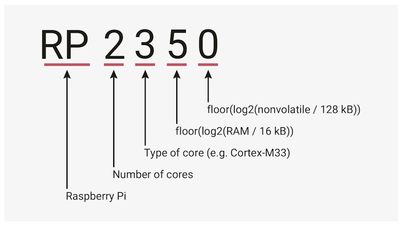
Naming convention for RP series of MCUs. Source: Raspberry Pi
The larger QFN80 package opens up more GPIOs from 30 to 48, and the RP2354 versions add 2MB of internal flash memory, being otherwise almost identical in behavior to non-flash versions.
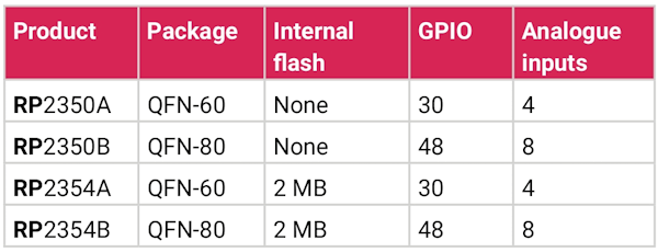
RP235x series' four packaging variants with differences. Source: Raspberry Pi
The free and open-source EDA software suite, KiCad, like Raspberry Pi, has no shortage of fans and a thriving community consisting of both hobbyists and professional s. The open, community-driven approach means that as RP2350 becomes more widely available, you can expect an abundance of early open-source design resources created using KiCad. These references will be invaluable as you develop your own RP2350-based projects. Even now, despite the lack of chips, the symbols and footprints for RP2350 chips are already freely available.
As with RP2040, Raspberry Pi have released minimal reference designs for RP2350 in KiCad 7.0 format, which is accompanied by a detailed hardware design guide. These resources are indispensable for engineers looking to design their own hardware with RP2350 but more importantly, the hardware guidelines advise early designers to follow very specific advice to ensure performance and stability. This includes replicating their switching regulator circuit as close as possible. Instead of recreating it and hoping for the best, KiCad users can literally copy it straight from the minimal design files, ensuring a perfect match and simplifying the process.
Along with KiCad's user-friendly interface, intuitive workflow, rich feature set and accessibility, it is no wonder KiCad has climbed the popularity ladder rivalling paid options. Coupled with the vibrant community and rich design resources, it is only natural that KiCad has become the go to solution for creating custom RP2350 boards.
NextPCB is currently offering an exciting opportunity for designers working with the RP2350 microcontroller. Through their NextPCB Accelerator campaign, they are sponsoring free prototype PCBs covering PCB manufacture, assembly and components - including early access to RP2350 chips.
Furthermore, you can get them even faster by selecting parts from their online components distributor, HQ Online. Thankfully, HQ Online stocks the key components Raspberry Pi requests in RP2350 designs, meaning you can start testing your designs in days. This is a truly too-good-to-miss opportunity to accelerate your product development with RP2350.
In the following discussions, we will be drawing from Raspberry Pi's guidelines and reference designs with additional guidance for KiCad users. We have also provided a sample Bill of Materials (BOM) for RP2350 designs that includes the key components with suggested part numbers. Recommended parts and other parts used in the minimal designs are included so you can extract and reuse any section at your pleasure. Just pick and choose parts you want to use from the file to start building your own BOM.
We have also provided HQ Online product links for purchase options that are either in-stock or have a short lead time; have plenty stock and are low cost at the time of writing. By sourcing all your parts from HQ Online, you can shorten the lead time for NextPCB turnkey PCB assembly to days instead of weeks.
As mentioned before, the RP2350 family of chips consists of 4 different part numbers. Raspberry Pi provides two reference example layouts for RP2350, one for the QFN-60 package (RP2350A), which is similar to the RP2040 design and one for the larger QFN-80 package (RP2350B). The onboard flash circuitry can easily be omitted for internal flash configurations.
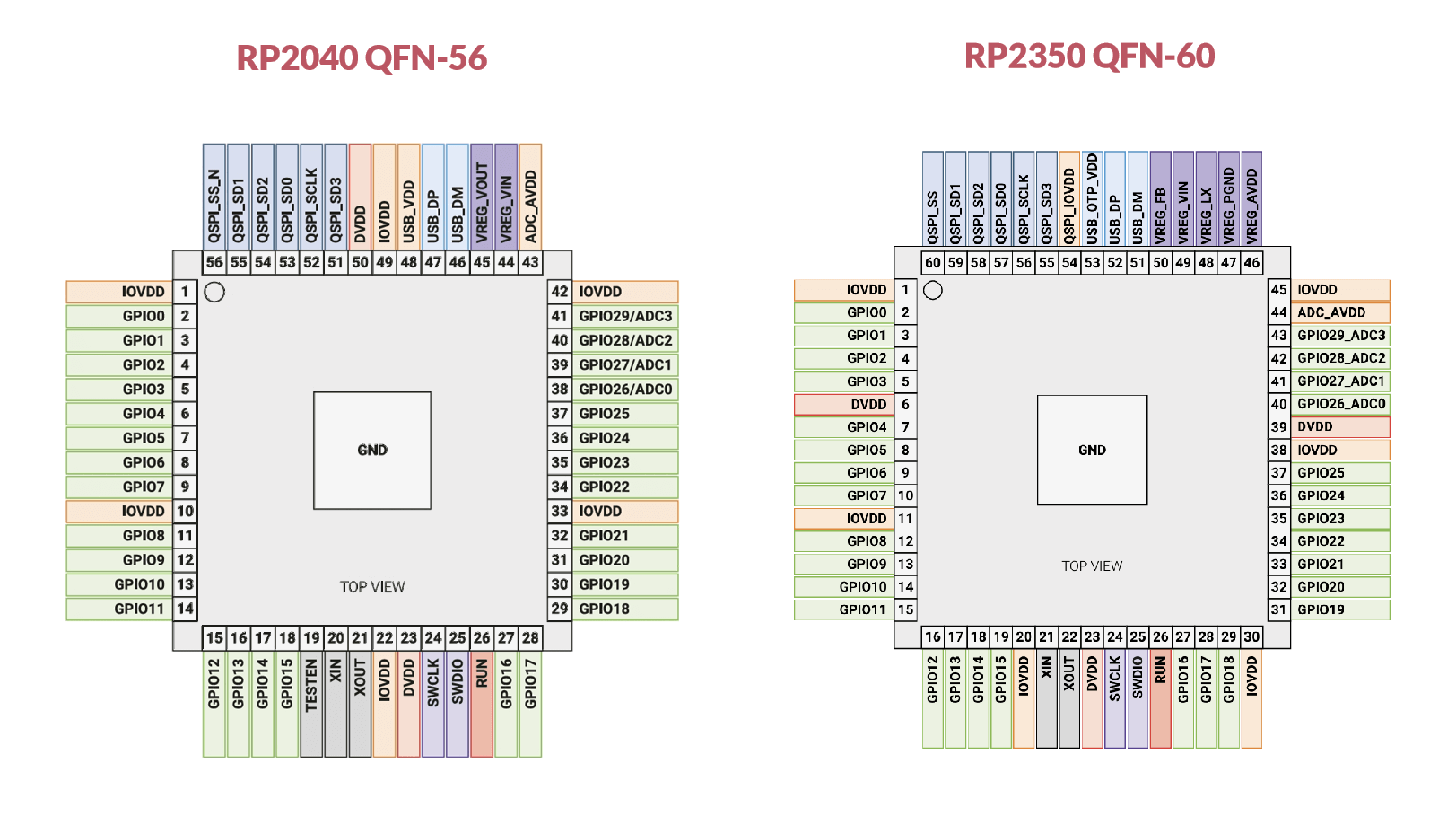
The A variants have a QFN package with the same body size as the RP2040 chip. While they have the same number of GPIOs and dimensions, note that the original RP2040 chip comes in a QFN-56 package as opposed to RP235xA's QFN-60 package. Therefore, the RP235xA are not a drop-in replacement for RP2040. RP2350 has an extra pin on each of the four sides of the package for the additional features.
Because of the additional pin on each side, the pins on the original RP2040 sit between those of the RP2350 chip. So even though the pin-outs are largely the same on the two chips, those upgrading existing designs will need to re-route all the traces to some extent.
They are still 0.4mm pitch parts with the leads on the underside of the body, so Raspberry Pi strongly suggests machine assembly. There are plenty of low-cost prototype manufacturing services that can take care of the job. Also, the recommended layout uses plenty of 0402-sized passives spaced relatively close together which can be a challenge to place manually let alone solder with an iron.
The KiCad design package provided by Raspberry Pi includes the schematic, symbols and footprints used. So you can import these into your symbol and footprint libraries and use them directly. If, for whatever reason, you would like the individual footprints or another footprint source for the chips, they are available on GitHub courtesy of HDR, though they mention they have not been fully tested.
As emphasized by Raspberry Pi, the most critical part of an RP2350 layout is the core voltage regulator. For RP2350, they have replaced the linear voltage regulator in favor of a switching regulator. While more complex, the switching regulator allows RP2350 to be more efficient at high and low loads.
The developers have spent no shortage of engineering hours tweaking and perfecting the layout and strongly suggest designers use this exact layout. Following their tried and tested recommendations can save you hours of additional work, and ensure optimal performance and system integrity. Luckily for KiCad users, they can use this layout directly either by copying it across to your design or creating a copy of the minimal design and subtracting unwanted parts.
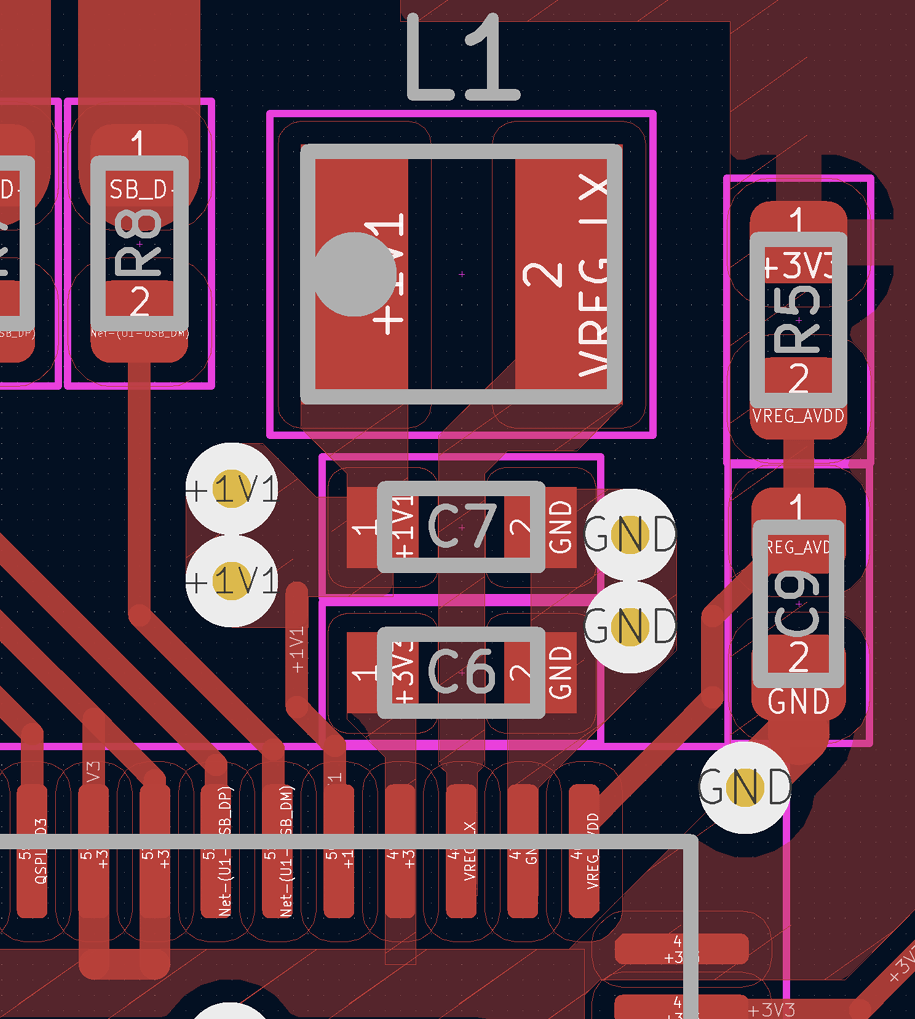
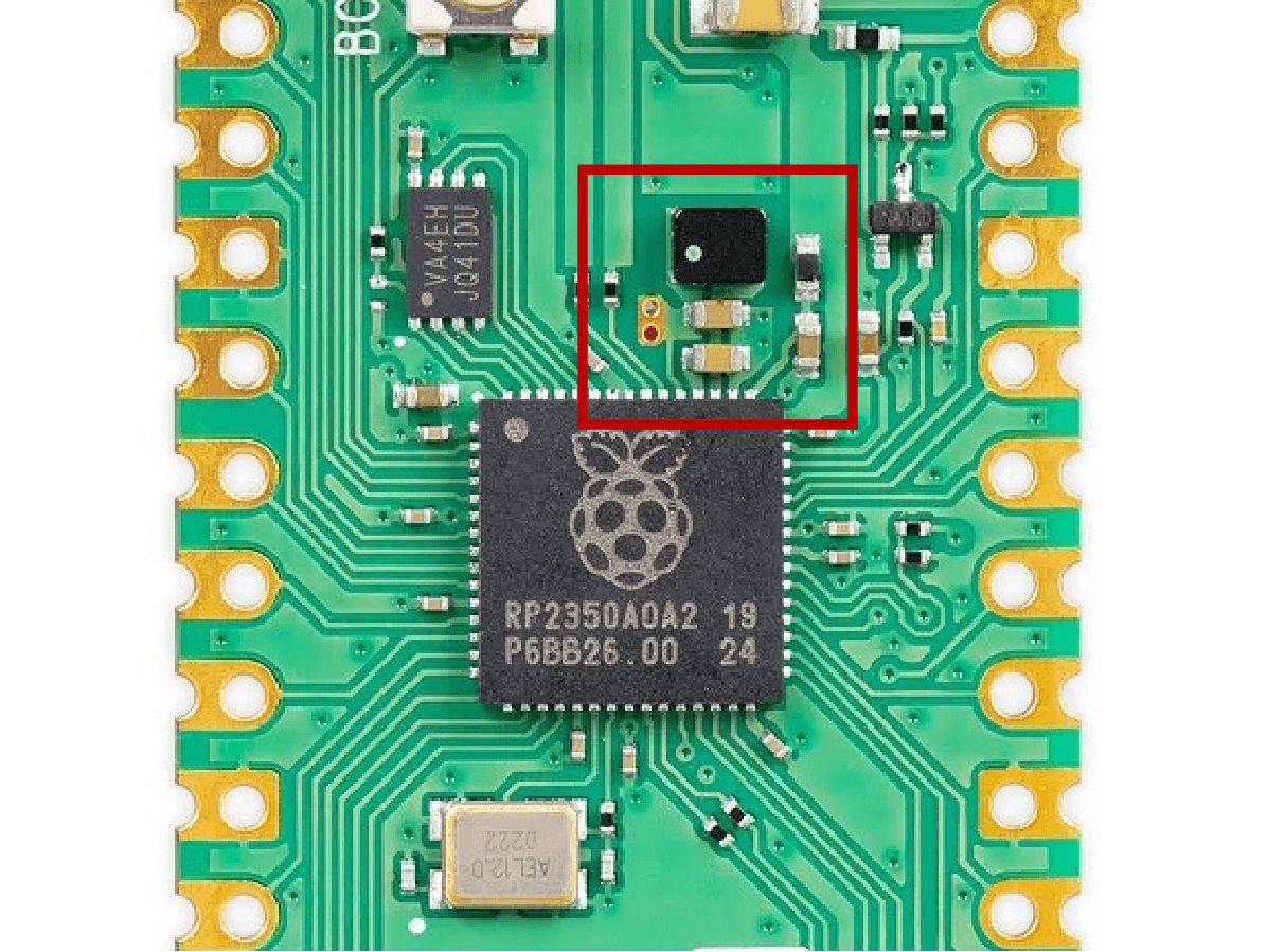
With KiCad, you can copy Raspberry Pi's tried and tested regulator layout as seen on the Raspberry Pi Pico 2 series.
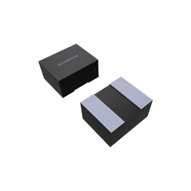
In addition to following the circuit layouts exactly, designers should also use the custom inductor AOTA-B201610S3R3-101-T from Abracon specifically for RP2350 boards. It has a fixed polarity and polarity marker and is widely available with major distributors including HQ Online.
An external crystal circuit is highly recommended for a more stable frequency source. At present, RP2350 has been qualified with the 12MHz ABM8-272-T3 crystal oscillator by Abracon, so early designers should use this part in their designs until more parts are qualified. Thankfully, this part is the same part suggested for RP2040 designs, so these are already widely available. HQ Online also has this part in stock.
The minimal designs use the NOR flash memory chip W25Q128JVSIQTR from Winbond. This can be used for both primary and secondary memory options in both external and internal memory options. Raspberry Pi provides memory requirements for other chips that should be compatible, however, be sure to check the recommended circuitry for guidance on pull-up resistors etc.
For input power, the minimal design borrows the circuit from RP2040 minimal design for simplicity. While this is not the circuit used in Pico 2, this is a completely viable solution for most applications. It uses the NCP1117 from Onsemi which is widely available and cost effective.
Similar to the Pico 2, the minimal design uses a USB-B connector with impedance matched data lines to satisfy the differential 90Ω requirement for USB. The BOM file contains a USB connector matching the same footprint, so for simple two layer designs, the whole circuit can be copied and reused. Just ensure the bottom layer is used a ground reference without splits and that the board thickness is 1.0mm.
For different stack-ups and board thicknesses, the correct trace widths can calculated either using KiCad's built-in calculator under Calculator Tools -> High Speed -> Transmission Lines or other widely available impedance calculator tools. NextPCB has an online impedance calculator tool for batch calculations following real NextPCB stackups.
The RP2350 documentation also has part suggestions for other parts including coupling capacitors and damping resistors which are also included in the BOM. Part suggestions for headers and buttons have also been included for those who want to produce the minimal design as is.
Headers
For the headers, there is no specific part referenced in the reference design however, 2x52 and 2x36 female headers are hard to come by or can be very expensive, with options from popular brands in excess of 5 USD a piece for the former. Of course, there is no reason for using such a large header in the minimal designs apart from the convenience of footprint selection, since you will likely only be using them for inserting jumper wires.
If you want to keep the same footprint, a common method of reducing costs is to build up the larger header using smaller cheaper headers. Just ensure there is enough room between adjacent headers and that they are aligned when soldering, especially if they are to be used in a shield fashion.
For this purpose, we have included 2x26 pin female headers in the BOM to make up a 52-pin header, and 2x9 pin headers to make up the 2x18 pin headers. Both options cost less than 1 USD for two pieces from HQ Online and are readily available.
Buttons
Likewise, the buttons on the minimal design are simply quality-of-life additions and can easily be replaced with a button of your choice. In the BOM, we have included the part used in the design and a cheaper substitute that uses the same footprint.
Once you have completed your design, be sure to take advantage of NextPCB's Accelerator campaign and get free PCBA prototypes and early access to RP2350 microcontrollers.

- Hardware Design with RP2350
- RP2350 Datasheet: 6.3.8. External Components and PCB layout requirements
- Minimal RP2350A and B reference design in KiCAD (KiCad 7.0 Design files)
- Suggested Parts and BOM for Raspberry Pi RP2350 Minimal Design - NextPCB (Google Spreadsheet)
Still, need help? Contact Us: support@nextpcb.com
Need a PCB or PCBA quote? Quote now
|
Dimensions: (mm) |
|
|
Quantity: (pcs) |
|
|
Layers: 2 |
Thickness: 1.6 mm |
|
|
|

 Printed Circuit Boards
 Surface

