
 PCB Assembly
 Layer Buildup
 Online Tools
 PCB Design-Aid & Layout
 Mechanics
 SMD-Stencils
 Quality
 Drills & Throughplating
 Factory & Certificate
 PCB Assembly Factory Show
Certificate
PCB Assembly Factory Show
Certificate
Support Team
Feedback:
support@nextpcb.comPower transistors are needed when driving high-current loads such as motors since they can handle amps of current. It is more often used BJTs and MOSFETs, but if more than a couple of amps are required, then the Darlington pair is very efficient. With Darlington pairs, the current gain of two transistors is coupled in one high gain, to make a low current signal to control high currents in the final transistor. In this article, the author intends to discuss the design and implementation aspects that relate to using Darlington transistors for driving higher power loads such as DC motors. In this article, we will discuss transistor selection, drive circuits, protection circuits, and example projects to apply Darlington pairs.
To simplify let’s begin with the initial step that involves selecting the right Darlington transistors for the task at hand. There are critical parameters that should be considered and they are the collector current rating which is the amount of current that the transistor can handle safely, saturation voltage which is the amount of voltage that will be dropped across the transistor in the state where it is fully turned on and the current gain which tells how much current the Darlington pair amplifies.

Assume that our motor consumes 5 amps of current for it to run. Hence, to be safe we will need Darlington transistors with a minimum of that much continuous collector current. There are many types of transistors available including 2N6065 as it has been observed that it can handle up to 6 amps DC. There is also a 2N6064 used which is also common with 4A capabilities.
It's generally a good idea to allow some headroom above the exact motor's current rating too. Motors can sometimes draw surges of current on startups that exceed their continuous rating. Having transistors rated for 1.5-2 times the motor current helps ensure they stay within their safe operating area.
Saturation voltage is important because it determines how much voltage will be wasted when the Darlington is on. Lower is better, with popular types like the 2N6065 having maximum VCE(sat) ratings of around 1.2 volts. This leaves enough overhead for voltage drops elsewhere in the circuit without compromising motor speed.
Current gain tells us how small of a base current is required to fully turn on the Darlington pair. High gains upwards of 1000x allow even small microcontroller outputs to control many amps of collector current. Proper gain enables the Darlington to efficiently act as a switch for the motor.
Those key parameters give us a starting point to shortlist suitable Darlington transistor options. From there, factors like package type, pricing, and availability help determine the final part selection. With the right transistors in hand, we're ready to begin designing the motor driver circuit.
The basic components of a Darlington pair motor driver include the Darlington transistors themselves, flyback diodes for free-wheeling the motor coils, and base drive resistors. A schematic of a simple single-ended drive circuit is shown below:
When the microcontroller output goes high, current flows through R1 and into the Darlington base. This strongly amplifies the drive current supplied by the micro through the microcontroller and fully saturates the Darlington switch. It connects the motor to the positive supply rail, powering it in one direction.
Bring the microcontroller output low and the Darlington turns off, disconnecting the motor from power. The flyback diode now provides a return path for motor back-EMF currents to flow through harmlessly. By alternately switching the Darlington pair on and off, the motor can be driven bidirectionally with only this simple circuit.
While the basic topology works well, there are some protections and enhancements that can improve the robustness and performance of the design:
Implementing these additional protections, feedback paths, and drive options turns the basic Darlington pair motor driver into a much more robust and versatile power-switching module.
Getting the base drive characteristics of the Darlington pair just right is important for efficient, reliable operation. We must provide adequate ON drive and turn-off speed while avoiding excessive base current demands that could damage the transistors.
The key parameters are the base drive resistor value, microcontroller output voltage/current, and Darlington gain/switching speeds. Pulling these variables together to determine ideal drive characteristics is an analytical process involving transistor specification sheets and test/measurement.
Starting with a typical Darlington like the 2N6065:
We'll use a 5V microcontroller output to drive the bases. With a desired collector current of 5A to turn our motor:
Ic/hfe = minimum base current required = 5A/1000 = 5mA
The microcontroller spec may list its output pin capabilities as well. A common micro can source/sink around 25mA, which leaves plenty of headroom to supply our 5mA base demand.
Using Ohm's Law, we select a base resistor value that will limit the base current while still fully turning ON the Darlington:
R = (Vmicro - Vbe) / Ib
Where Vbe is the typical base-emitter turn-on voltage of the transistor (~0.7V)
Plugging in numbers:
R = (5V - 0.7V) / 0.005A = 900 ohms
We round down to the nearest standard resistor value of 820 ohms. This resistor will allow 5mA of base drive from a 5V source, within safe transistor limits. Now we have characterized the ideal drive conditions for this Darlington transistor/microcontroller pair.
The same process can be followed for other Darlington/driver configurations to develop a base drive schematic optimized for reliable, efficient switching. Periodic testing is also advised, to verify design assumptions against real-world performance over time and varying conditions like temperature.
Let's conclude by exploring a few example projects demonstrating how these Darlington pair motor driver concepts come together in real applications:
Electric motors operate by utilizing the interaction between magnetic fields and conductors to transform electrical energy into rotational mechanical motion. There are three main categories of electric motors:
Alternating current (AC) motors- In these motors, the magnetic field is produced by alternating currents in a coil wound around the stator.
Direct current (DC) non-stepper motors- These motors use direct current to generate a magnetic field in the stator. The rotor is not designed to rotate in discrete steps like a stepper motor.
Direct current (DC) stepper motors- DC stepper motors have a stator and rotor with energized pole pieces that cause the rotor to rotate slowly and in discrete angular increments or "steps" as the fields are switched on and off.
Alternating current (AC) motors are used in high-power single-phase or multi-phase industrial applications where a constant rotational torque and speed are required to control large loads. Examples include fans, pumps, and other applications that require consistent rotation to adequately handle substantial loads. AC motors provide rotational force through interaction between their magnetic stator fields and the current-carrying conductor fields of the rotor. They are well-suited for operations demanding steady torque and velocity control of sizeable mechanical systems, as discussed in the 1998 Wunderlich Lecture notes on topics like AC power delivery, single-phase versus three-phase current, and types of AC motors such as induction motors.
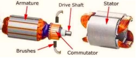
Direct current (DC) motors are among the most commonly used actuators that enable continuous motion whose speed can be easily regulated, making them ideal for applications requiring velocity management, servo-like guidance, and/or positional control. A DC motor comprises two main components: the stationary stator, and the rotating rotor. The motor functions by using a direct electric current to generate a magnetic field in the stator, while the rotor is made to spin through interaction with this magnetic field. DC motors are well-suited for tasks involving precision control of rotational velocity, such as in servo mechanisms, due to the simple regulation of rotor rotation made possible through adjusting current flow in the stator.
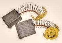
Replacing the brushes can be difficult as they are spring-loaded internally, requiring the motor to be disassembled for access. From my experience repairing research robots, large building systems, and automobiles, brush replacement within these motors presents a challenge. Since the brushes are located inside the motor body and held in place with springs, the motor housing must be opened to access the brushes when they need replacing due to wear over time. The internal and spring-loaded nature of the brushes means removal and installation involves a multipart disassembly/reassembly process. While brushed DC motors provide advantages in cost and simplicity, brush replacement proves troublesome given that repairs necessitate taking the motor apart to access these worn items tucked within.
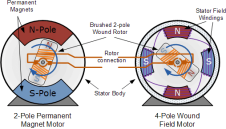
In this motor variety, a magnetic field is generated within the rotor via permanent magnets affixed to it. These motors tend to be more costly yet more compact than typical brushed DC motors, as they employ "Hall effect" switches located on the stator to induce the necessary sequence of the stator field's rotation. However, they offer superior torque/speed profiles, greater efficiency, and a longer functional lifespan compared to equivalent brushed DC designs. The stator's magnetic field can be created either by wound field coils or permanent magnets. Despite a higher price point, brushless DC motors provide benefits such as better performance characteristics and increased durability, making them worthwhile for applications where these advantages are paramount over bare minimizing of expenses.
In DC non-stepper motors, the rate of rotation is determined by the applied DC voltage, while the output torque depends on the current through the motor windings. By coupling them to gearboxes or gear trains, the output speed can be decreased while simultaneously increasing torque at a higher velocity. Small DC motors can be switched "on" or "off" using switches, relays, transistors, or MOSFET circuits. The simplest form of control is "linear" control using a bipolar transistor as a switching device to govern the motor from a single power source. Alteration of the base current feeding into the transistor allows for variable motor speed - for instance, half base current provides half the supply voltage to the motor. Maximum current causes saturation, delivering the full supply voltage for faster rotation. With this linear approach, power is constantly delivered to the motor. Control is exerted by modulating transistor conduction based on the control signal.
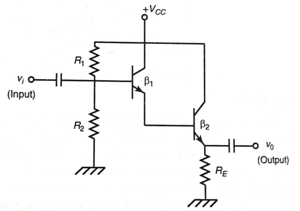
This simple circuit diagram illustrates uni-directional speed regulation for a DC motor. Since rotational velocity is proportional to the voltage across the motor terminals, that terminal voltage can be modulated using a transistor.
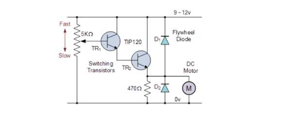
Two transistors are connected in a Darlington configuration to control the main armature current. A 5kΩ potentiometer regulates the base drive to the first transistor TR1, which then controls the main switching transistor TR2. This allows the motor's DC voltage to vary from zero to the supply voltage (e.g. 9-12 volts).
Optional flyback diodes are placed across the switching transistor TR2 and the motor terminals for protection against back EMF generated by motor rotation. The adjustable potentiometer could be replaced with a continuous logic signal from a microcontroller or PIC port to fully turn the motor on/off.
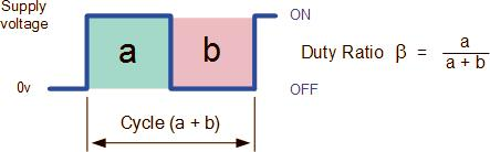
Beyond basic speed control, this circuit can regulate motor rpm by rapidly pulsing the motor current on and off at a high frequency. Speed varies between standstill (0 rpm) and maximum (100%) by adjusting the ratio of on-time (tON) to off-time (tOFF). This is achieved through pulse-width modulation (PWM), where the duty cycle (proportion of tON to the total period) is altered to fine-tune the average motor voltage and consequently its velocity.
As established earlier, a DC motor's rotational speed is directly proportional to the mean or average voltage at its terminals. The higher this average voltage is, up to the motor's maximum rating, the faster it will rotate. In other words, increased voltage produces increased speed.
By adjusting the ratio of the "on-time" (tON) duration to the "off-time" (tOFF) duration, referred to as the duty ratio, mark/space ratio, or duty cycle, the average motor voltage and consequently its rotational velocity can be modulated.
For basic unipolar drive configurations, the duty ratio β is represented as:
β = tON / (tON + tOFF)
Varying this ratio of pulse widths allows adjustment of the motor's effective operating voltage through PWM. This provides a means to precisely govern rotational speed for applications requiring fine control, as manipulation of the duty cycle impacts the mean voltage delivered to the motor terminals.
The mean DC output voltage fed to the motor is given by:
Vmean = β x Vsupply
By varying the pulse width a, the motor voltage and thus the power applied can be modulated. This type of control is called pulse-width modulation, or PWM.
Another control method involves changing the frequency (and period) of the controlling voltage while keeping the duty ratio times constant. This is called pulse frequency modulation, or PFM.
With PFM, the motor voltage is governed by applying pulses of variable frequency. At a lower frequency or fewer pulses, the average voltage applied is lower, resulting in slower speed. At a higher frequency or more pulses, the average terminal voltage increases, speeding up the motor.
Transistors can be used to regulate the power delivered to a DC motor, operating in either linear mode (varying motor voltage), PWM (varying pulse width), or PFM (varying pulse frequency). Modulating these parameters enables customized control of rotational velocity.
While controlling DC motor speed with a single transistor provides benefits, it also has a key drawback - rotation is always unidirectional in the same direction. Many applications require a bidirectional operation to move forward or back. To control direction, the polarity of the DC power applied to the motor connections must be reversed, causing the shaft to spin in the opposite direction. One simple and inexpensive way to govern rotational direction is with different switches arranged as follows:
By alternately opening and closing the switches S1 and S2, the direction of current flow through the motor windings and therefore the direction of shaft rotation can be reversed. When S1 is closed and S2 is open, current flows in one direction through the motor causing it to rotate in one direction. When S2 is closed and S1 is open, the current flows in the opposite direction making the motor shaft rotate in the reverse direction.
This switch-based approach provides an elementary yet effective solution for implementing reversible motor control using basic components.
This first circuit employs a single double-pole, double-throw (DPDT) switch to govern the polarity of the motor connections. By toggling the switch contacts, the supply to the motor terminals is alternated, causing the motor to reverse its direction of rotation. A DPDT switch allows both poles of the power source to be simultaneously reversed when the switch is thrown. Therefore, a single DPDT switch is sufficient to selectively reverse the polarity applied to the motor windings, accordingly reversing the direction of shaft rotation in a basic electromechanical bidirectional motor control scheme.
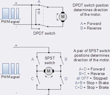
The second circuit employs four single-pole, single-throw (SPST) switches in an "H-bridge" configuration. The mechanical switches are paired up for switching and must be operated in a specific sequence to run or stop the DC motor. For example, switches A + D enable forward rotation while B + C enable reverse rotation, as shown. Combining switches A + B or C + D shorts the motor terminals, inducing rapid braking. However, simultaneously actuating switches A + C or B + D risks short-circuiting the power source.
It's important to note that these circuits can function without pulse-width modulation (PWM), relying solely on switch timing to control motor behavior.
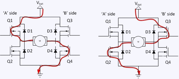
Bidirectional operation can also be achieved with a CMOS transistor H-bridge using power MOSFETs for switching and diodes for circuit protection instead of mechanical switches. This solid-state approach retains the operational principles of the switch-based H-bridge but trades mechanical parts for semiconductor components to regulate current flow and motor direction electronically.
NOTE: MAKE SURE YOUR CONTROL CIRCUITS OR CODE DOES NOT TURN ON AT THE SAME TIME BOTH OF THE FETS ON ONE SIDE OF THE H-BRIDGE.
For instance, in 1993 at the Applied Science and Engineering Lab (ASEL) of AI DuPont Children's Hospital, there was a mobile robot competition held between researchers that was televised on local Philadelphia television. The objective was for each robot to autonomously locate a hidden bright heat lamp somewhere in the hospital.
Weeks prior, my team had completed our robot and code for this challenge earlier than any other participants. However, on the day of the competition, a last-minute change to our code unexpectedly triggered unintended behavior. Just before our demonstration run, a minor tweak to the software caused the robot to malfunction on game day instead of performing as designed during extensive prior testing.
While we believed our robot was fully prepared, the final altered code led to unexpected operation when it mattered most during the televised contest. This demonstrated how even minor last-minute changes carried risks and that thorough validation was important before high-stakes events.
Bi-directional H-bridge Circuit using bipolar Transistors and Diodes for circuit protection:
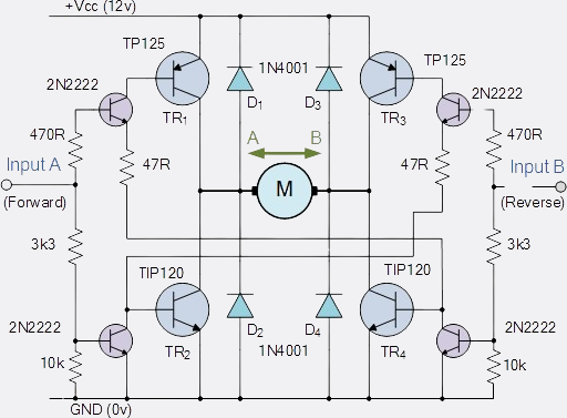
This H-bridge circuit gets its name from the H-shaped arrangement of its four switches, whether electromechanical relays or transistors, with the motor center. The transistor or MOSFET H-bridge is one of the most common designs for bidirectional DC motor control.
It uses complementary pairs of both NPN and PNP transistors in each leg, switched together in pairs to direct motor operation. Control input A rotates the motor forward while input B reverses it.
By toggling the "diagonal pairs" of transistors - TR1 and TR4 vs TR2 and TR3 - the motor's direction is selected. For example, when TR1 is on and TR2 off, terminal A connects to the positive supply voltage (Vcc), and with TR3 off and TR4 on, terminal B grounds. This orients the motor voltage polarity to rotate in one direction.
Reversing the switching states so TR1 is off and TR2 on, with TR3 on and TR4 off, switches the current flow and thus motor rotation to the opposite direction. Selective switching of the complementary transistor pairs facilitates reversible motor commutation via the H-bridge arrangement.
|
Input A |
Input B |
Motor Function |
|
TR1 and TR4 |
TR2 and TR3 |
|
|
0 |
0 |
Motor Stopped (OFF) |
|
1 |
0 |
Motor Rotates Forward |
|
0 |
1 |
Motor Rotates Reverse |
|
1 |
1 |
NOT ALLOWED |
No other transistor pair combinations must be activated simultaneously, as this could cause a short circuit drawing excessive current from the power supply. For example, switching both TR1 and TR2 on at once.
As with the uni-directional examples above, pulse-width modulation (PWM) can control rotational speed in this circuit as well. Combining H-bridge switching with PWM yields accurate control over both direction and velocity.
Integrated circuits like the SN754410 Quad Half H-Bridge or dual full-bridge L298N contain all necessary logic and safety features to facilitate H-bridge bidirectional motor control. With integrated controls and driver stages, these off-the-shelf decoder ICs simplify circuit design and are well-suited for applications requiring specialized reversible motor commutation. Their use avoids potential issues that can arise when building equivalent circuitry from discrete components.
Stepper motors are commonly used for precision robotic arm or manipulator control due to their ability to convert digital input pulses into discrete mechanical movements. Like DC motors, stepper motors are electromechanical actuators but function differently. A stepper motor is a type of synchronous, brushless motor with a multi-toothed permanent magnet rotor and a wound stator. It does not have a commutator or brushes. Stepper motors move in discrete rotational increments or "steps" rather than continuously like a DC motor.
The step angle, or amount of rotation per step, depends on the number of stator poles and rotor teeth. For example, a motor with 100 steps per revolution has a step angle of 360/100 = 3.6 degrees.
There are three main stepper motor types - variable reluctance, permanent magnet, and hybrid. Stepper motors are well-suited for applications requiring precise positioning, repeatability, and responsive speed/direction control.
Additionally, stepper motors can hold their position without power. This allowed precise robotic arm control in our 1993 work developing a master-slave telerobot for disabled children. Modern high-resolution steppers with accuracies under 0.9 degrees per step and multiple rotor teeth/stator poles are commonly used in magnetic storage and robotic systems. A 200-step, 1.8-degree motor is frequently used.
In summary, stepper motors convert digital pulses to incremental rotational movements, making them well-suited for precision motion control applications like robotic manipulators.
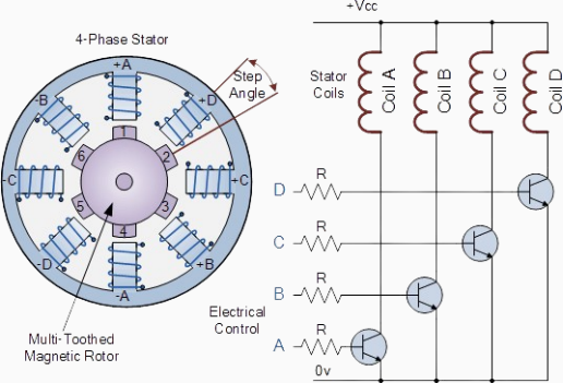
In this simple example of a variable reluctance stepper motor, a central rotor is surrounded by four coil phases labeled A, B, C, and D. Coils of the same letter are connected. Energizing a coil phase causes the magnetic rotor to align with that phase's poles. By powering each phase sequentially, the rotor is induced to rotate or "step" between positions set by its constructional step angle. The driver controls step angle and speed by powering phases in sequence - e.g. "ADCB, ADCB, ADCB, A..." for forward or "ABCD, ABCD, ABCD, A..." for reverse rotation.
This four-phase motor has eight stator poles spaced at 45 degrees, and a six-toothed rotor spaced at 60 degrees. With 24 pole-tooth combinations, one revolution equals 360/24 = 15-degree steps. Finer stepping is possible by connecting coils differently or implementing micro-stepping, though the latter requires expensive sinusoidal currents. Speed also varies via the digital pulse delay between phases - longer delays equal slower rotation for one revolution. By applying a fixed number of pulses, the rotor rotates through a known angle without feedback. This open-loop control simplifies design versus closed-loop systems.
For example, with 3.6-degree steps, 216 degrees would require 216/3.6 = 60 pulses. Precise positioning is achieved through pulse-driven, incremental motion.
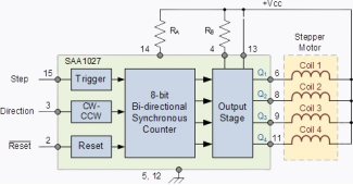
Many integrated stepper motor controller ICs are available to regulate step timing, rotational velocity, and direction.
One example is the SAA1027, which contains integrated counters, encoders, and sequencing logic to automatically pulse the four fully controlled bridge outputs in the correct order. The direction of rotation and modes like a single step or continuous rotation in the selected direction can be specified. However, continuous rotation places an additional load on the controller. 8-bit digital controllers enable up to 256 micro steps per full step, providing very fine positional resolution. Microstepping increases steady-state torque but requires a more capable driver. IC-based motor controllers handle complex stepping routines, freeing up the primary processor for other tasks. By managing commutation internally, they simplify the implementation of closed-loop stepper motion control schemes. The SAA1027 demonstrates how an integrated circuit can handle complex stepping sequence generation and H-bridge driver management, allowing digital controllers to focus on higher-level motion profiles and coordination.
A popular first design is a 3-phase brushless DC motor controller. Brushless motors require electronic commutation to power each phase with the proper timing sequentially.
A microcontroller measures the back-EMF zero-crossings in each phase to determine the rotor position. It then uses this feedback to generate the 6 PWM signals needed to drive the 3 half-H-bridge circuits via 3 Darlington pairs.
Thermistors on each transistor provide over-temperature protection. A current sense resistor monitors the overall motor current. The motor is run in speed control mode by adjusting PWM duty cycles based on desired RPM input.
For robotics, a dual H-bridge Darlington module can independently control 2 DC motors for differential drive mobility. Two microcontroller ports generate left/right motor direction and speed signals.
Braking is enabled by actively connecting each motor back across the supply during rest periods for dynamic stops. An I2C interface allows the driver module to communicate status/fault data to the main robot controller board.
A CNC machine uses stepper motors, servos, or a higher-power AC/DC spindle motor to drive cutting/engraving tools. A Darlington module rated for 10-15A spikes the spindle requires switches multiple high side/low side pairs for full-bridge control.
Thermal cutbacks smoothly limit speed under heavy loads to prevent over-torquing/stripping. An encoder measures back-EMF for closed-loop commutation and precise speed regulation during cuts at various feed rates.
These illustrate just a sampling of the versatile motor control applications where Darlington transistor drivers truly shine. Their unique ability to efficiently control larger currents from smaller triggering signals makes them well-suited for myriad motion control and automation system designs.
One common application for Darlington transistor motor drivers is in robotic actuators and mobile robots. A dual full-bridge design allows independent control of two DC motors to provide differential drive locomotion.
A basic schematic of such a dual H-bridge motor driver module is shown below. Two full bridges are used, one for each motor phase. Each bridge incorporates an N-Channel MOSFET or PNP Darlington pair for the high-side switches and a complementary NPN Darlington for the low side.
This configuration enables both motors to run freely in either the forward or reverse direction. Four inputs from the microcontroller determine the operating mode - two for direction and two for speed/PWM control of each motor independently.
With the Darlington pairs capable of handling currents upwards of 5-10A continuous, this module could power two reasonably sized DC geared motors for a robot of perhaps 10-15 lbs in weight. Larger robot designs may require even higher current Darlingtons in the 15-20A range.
Braking Capability
Adding a pair of Darlingtons and flyback diodes to each motor terminal allows dynamic or regen braking control. During rest periods, the microcontroller actively connects each motor back across the power rails.
This provides braking torque to slow or stop the robot smoothly without relying on friction alone. It also recaptures some of the kinetic energy back into the battery during deceleration.
Thermal Protection
Temperature sensing monitors the heat sinks or near the Darlington cases. A thermal cutoff disables the outputs if any transistor exceeds a safe operating temperature, preventing damage from sustained heavy loads or lack of airflow.
Communications Interface
A serial bus like I2C or SPI allows the motor driver module to communicate operational parameters, fault conditions, and feedback sensors back to the main robot controller. The controller can adjust operation accordingly based on real-time system status.
Feedback Inputs
Adding encoders, inclinometers, or other feedback sensors to the module provides closed-loop control data to the micro. Features like PID speed regulation or automatic leveling/balancing become possible based on positional or orientation inputs.
With these key design elements, the Darlington H-bridge module fulfills all the motion control needs for a sophisticated robotic platform. Dual independent DC motor phase drives, braking control, protection features, and instrumentation through an onboard micro create an elegant all-in-one solution.
Computer-controlled machining centers represent another core application area for high-current Darlington motor drivers. Tasks like drilling, milling, and cutting require precisely regulating rotational speeds under varying load conditions.
A high-power AC or DC spindle motor lies at the heart of any CNC system. Driving this inductive load smoothly across a wide speed range requires an efficient full-bridge topology. Darlington transistors provide the current handling to interface directly between a lower-power microcontroller and several kilowatts of spindle power.
A conceptual diagram of a CNC machine spindle controller module using Darlington pairs appears below:
Key aspects of such a controller design include:
Dual 19A Darlington pairs in an H-bridge arrangement supply up to 400VAC 3-phase or 60VDC motors.
Encoder feedback on the motor maintains closed-loop rotational velocity control during position-based cutting paths.
Thermal sensors protect Darlingtons from overheating during extended heavy-duty cycles by limiting output PWM duty cycle.
High-side drivers boost control signals to sufficiently gate larger N-channel MOSFETs or Darlingtons for higher voltage operation.
Control interfaces allow the module to connect to machine CNC controls for positional commands, and spindle speed/torque setpoints.
Properly designed with robust Darlington switching, modular interface options, and closed-loop control ability, such a controller empowers DIY or OEM CNC systems with high-performance spindle control directly from a microcontroller. Their high current prowess makes Darlington transistors a natural fit for this demanding industrial automation role.
In summary, Darlington pairs allow microcontrollers and other low-power electronics to directly drive and commutate motors, actuators, and various high-current loads through a straightforward drive circuit topology.
By selecting devices rated for the targeted load current plus adequate headroom, adding protective snubbing and feedback sensing, and optimizing the base drive characteristics, a robust Darlington transistor motor driver module can be developed.
Proper transistor and circuit design maximizes efficiency while safely operating the power switches within their thermal and electrical limits. This enables creative automation and mechatronic projects requiring controlled high-current switching that might otherwise require more complex solutions.
With Darlington pair technology, virtually any motorized mechanism can become an electromechanical system powered directly by microcontroller-based intelligence. They provide a simple yet powerful building block for designers to tap into when applications demand efficiently controlling larger currents with smaller control signals.
Still, need help? Contact Us: support@nextpcb.com
Need a PCB or PCBA quote? Quote now
|
Dimensions: (mm) |
|
|
Quantity: (pcs) |
|
|
Layers: 2 |
Thickness: 1.6 mm |
|
|
|

 Printed Circuit Boards
 Surface

