
 PCB Assembly
 Layer Buildup
 Online Tools
 PCB Design-Aid & Layout
 Mechanics
 SMD-Stencils
 Quality
 Drills & Throughplating
 Factory & Certificate
 PCB Assembly Factory Show
Certificate
PCB Assembly Factory Show
Certificate
Support Team
Feedback:
support@nextpcb.comWhat is the Current Divider Rule? And when and how to use the Current Divider Rule? Before, you can understand the Current Divider Rule, make sure you know these basics:
Ohm’s Law "V=IR"
KCL "Kirchhoff’s Current Law" and
Voltage Divider
If you don't know what "V=IR" means as Current Divider Rule “CDR” is a direct consequence of Ohm’s Law, and you do not understand how voltage and current behave in series and parallel circuits, then you will not be able to solve complex circuits or even the simplest ones.
These are the basics of engineering. I remember learning all this in the first year of engineering. And believe me, I still use this knowledge today because series and parallel connections are in every circuit.
First, I will help build your foundation, and then we will move forward with the Current Divider Rule Formula.
V = IR is known as Ohm's Law; which is a fundamental principle in electrical engineering. It relates the voltage “V” across a resistor to the current “I” flowing through it and the resistance “R” of the resistor.
V is the voltage across a resistor and it is measured in volts “V”.
I is the current flowing through a resistor and it is measured in amperes “A”.
R is the resistance of a resistor and it is measured in ohms “Ω”
If you know the value of current “I” and Resistance “R” then you can find the value of Voltage. In simple words the formula V=IR can be rearranged to solve for any of the three “Voltage, Current, and Resistance”.
Ohm's Law can be used to calculate any one of these quantities if the other two are known. It is essential for understanding how electrical circuits behave and is widely applied in both theoretical and practical scenarios.
In mathematical terms, Ohm's Law can be rearranged to solve for any of the three variables:
You must know about the ohm’s law because; it is with the help of this law we can design and analyze electrical and electronic circuits. This Law allows engineers to predict how a particular circuit will respond to different voltages, currents, and resistances.
Now, you might be wondering how to practically use it.
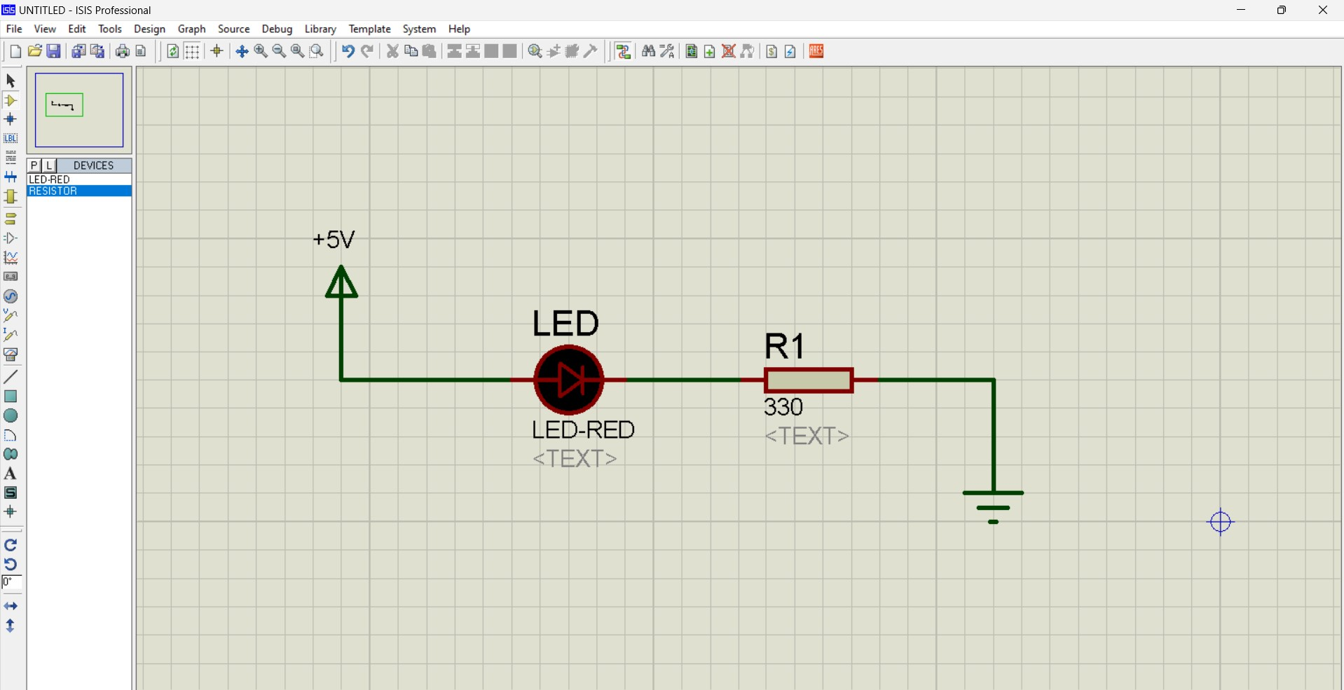
You have probably noticed that when we power up an Arduino, ESP32, ESP8266, or any other circuit, an LED on the board turns on. This LED indicates that the circuit is powered on. Usually, we provide 12V or 5V as input, but the LED typically operates between 2V and 3V. Although there are LEDs with higher voltage ratings, the ones on circuits are usually 2.5V. I personally use 2.5V LEDs as well.
Real-World Example:
Now the question is, how to safely power up this 2.5V and 20mA LED with a 5V power supply? We need to find the value of R1.
Ans:
We can find the value of R1 using the Ohm’s Law.
V=IR
The values of Voltage and Current are given
V (Supply voltage) is 5 Volts.
Led voltage is 2.5 volts.
I (LED current) is 20mA.
So by re-arrange the V=IR formula
R = V/I
R = ( 5 – 2.5) / 20mA
R = 2.5/20mA
R = ( 2.5 * 1000 ) / 20
R = 125 Ohms
You will need a resistor of 125 ohms to power the LED. If you use a resistor that is less than 125 ohms, your LED will burn out. And if you use a resistor with a higher value, your LED won’t turn on.

So, what I usually do is use a resistor with a slightly higher value than the calculated one. For example, instead of a 125-ohm resistor, I use a 330-ohm resistor. This way, the LED doesn't get too hot and its lifespan increases.
And as we increase the resistor's value, the LED's brightness will decrease. Eventually, there will be a point when the LED won't turn on at all. This happens because the high resistance causes most of the voltage to drop across the resistor, leaving no voltage for the LED.

You can see, now that I have connected a 10K resistor in series, the LED is not turning on anymore. I think by now you have a good understanding of Ohm's Law.
When I first heard about the Current Divider Rule, Kirchoff’s Current Law immediately came to my mind because I had already studied Kirchoff’s Current Law. So, it’s normal if you also think of Kirchoff’s Current Law.
Kirchoff’s Current Law (KCL) and the Current Divider Rule (CDR) are both very important concepts in engineering. However, you should not get confused between them because, although they are related, they have different purposes.
Kirchhoff's Current Law “KCL”:
According to Kirchoff’s current Law “KCL” the total current entering a node (junction) in an electrical circuit must equal the total current leaving the node. Essentially, the sum of currents flowing into the node is zero. KCL is a key principle for circuit analysis.
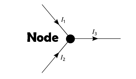
So, according to the KCL
I3 = I1 + I2
∑ Iin = ∑ Iout
Current Divider Rule “CDR”:
With the help of the Current Divider Rule, we can calculate the current flowing through each branch in a parallel circuit. According to the Current Divider Rule “CDR”, the current through a specific branch is proportional to the total current entering the node and the resistance of that branch, divided by the total resistance of all parallel branches combined.
The Current Divider Rule is given by:
Ix = Itotal X ( Rtotal /Rx)
Ix is the current following the Rx resistor or branch x.
Itotal is the total current entering the parallel combination.
Rx is the resistance of the branch through which Ix is calculated. And
Rtotal is the total resistance of all the branches.
Basically, the Current Divider Rule has been derived from Kirchoff’s Current Law to make it easier for engineers and other electronics professionals to analyze parallel circuits.
When you see the Current Divider Formula, you might also think of the Voltage Divider Formula. If you do, your mind is quite sharp. But remember, you should not mix up the Current Divider Formula and the Voltage Divider Formula because they are very different concepts. The Current Divider Formula is used for calculating and distributing current, while the Voltage Divider Formula is used for calculating and distributing voltage.
By now, you should understand that the Current Divider Rule (CDR) is used to determine how current is distributed across parallel resistances in a circuit, while the Voltage Divider Formula deals with the distribution of voltage across resistors connected in series. Both formulas use Ohm’s law and are essential tools for analyzing both simple and complex electrical circuits.
How to use the Current Divider Formula? To explain this, let’s find the current flowing through different branches.
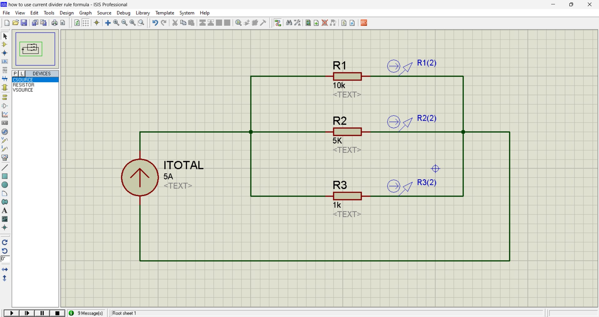
We have a total of three resistors connected in parallel.
R1 = 10K
R2 = 5K
R3 = 1K
Itotal = 5A
We need to find the current I1 flowing through the resistor R1, I2 flowing through the resistor R2, and I3 flowing through the Resistor R3.
I1 = ?
I2 = ?
I3 = ?
Let’s first find the total resistance.
To find the total resistance Rtotal of resistors (R1, R2, R3) connected in parallel, we can use the following formula.
1/Rtotal = ( 1/R1 + 1/R2 + 1/R3)
Given:
R1 = 10KΩ
R2 = 5 KΩ
R3 = 1 KΩ
Let’s calculate Rtotal
1/Rtotal = 1/10,000 + 1/5,000 + 1/1,000
1/Rtotal = 0.0001 + 0.0002 + 0.001 = 0.0013
Now, let’s take the reciprocal to find Rtotal:
Rtotal = 1/0.0013 ≈ 769.23Ω
So, the total resistance Rtotal is approximately 769.23 ohms.
Rtotal = 769.23 Ω
We also know, the total current entering into the parallel branches is 5A.
It = 5A.
As I explained earlier, the Current Divider Formula is given by
Ix = Itotal X ( Rtotal /Rx)
So, to find the current through the resistor R1, the above equation will become;
I1 = It × ( Rtotal / R1)
I1 = 5 ( 769.23 / 10,000)
I1 = 0.38462A
Now, let’s find the current flowing through the resistor R2.
I2 = It × ( Rtotal / R2)
I2 = 5 ( 769.23 / 5,000)
I2 = 0.76923A
Now, Let’s find the current flowing through the resistor R3
I3 = It × ( Rtotal / R3)
I3 = 5 ( 769.23 / 1,000)
13 = 3.84615A
Now, if you add all these currents, it should be equal to 5A; if not then the calculations are wrong.
It = I1 + I2 + I3
It also satisfies the Kirchoff’s Current Law.
It = 0.38462 + 0.76923 + 3.84615 = 5A
It = 5A
Let’s confirm this through the Proteus simulation.
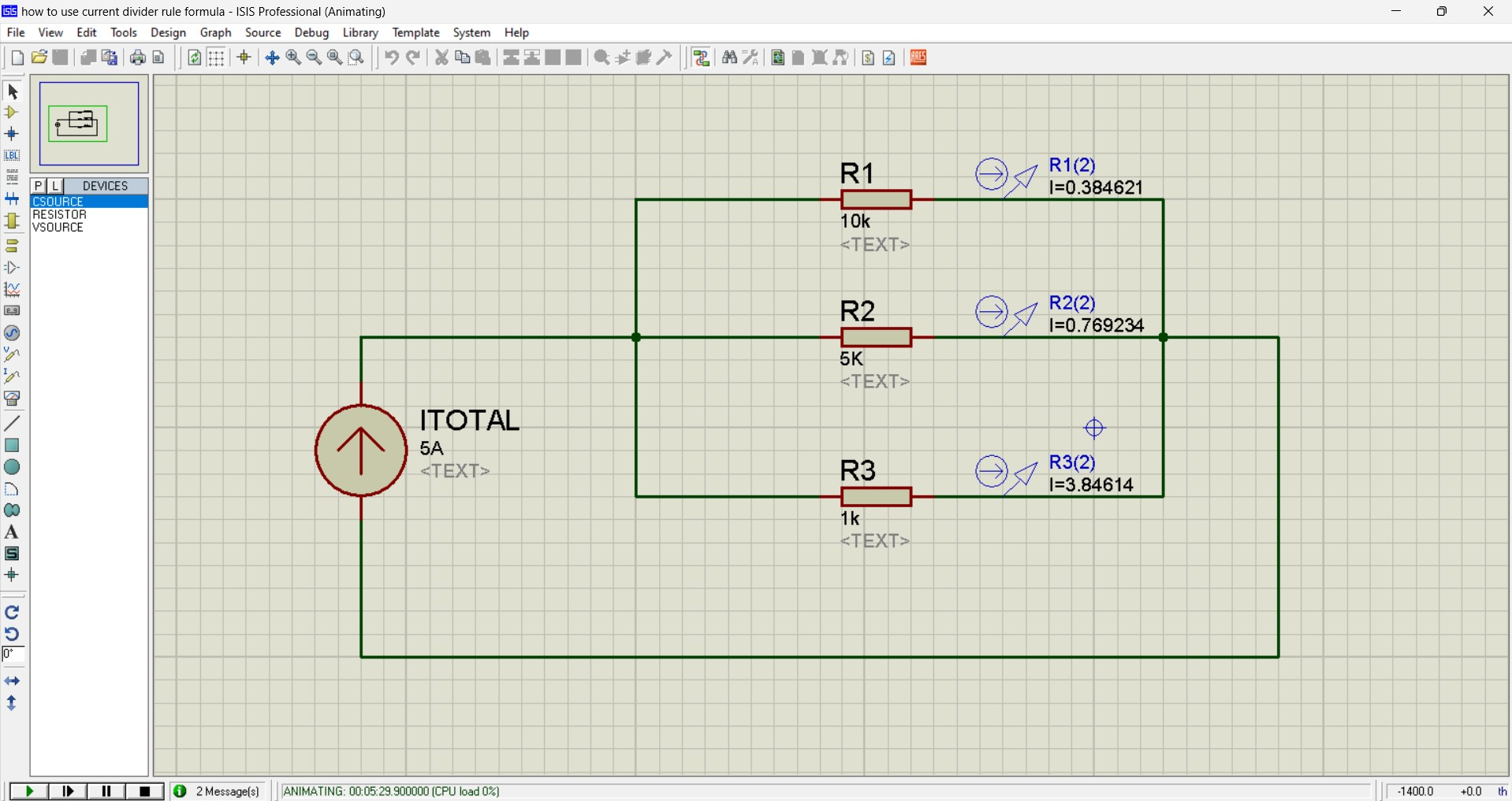
Even in the simulation, you can see the same amounts of currents are flowing through all three branches. So, this is how effectively you can use the Current Diver Formula.
Still, need help? Contact Us: support@nextpcb.com
Need a PCB or PCBA quote? Quote now
|
Dimensions: (mm) |
|
|
Quantity: (pcs) |
|
|
Layers: 2 |
Thickness: 1.6 mm |
|
|
|

 Printed Circuit Boards
 Surface

