
Support Team
Feedback:
support@nextpcb.com
In KiCad EDA, the Import Settings feature allows you to import or copy board settings across designs freely. But this handy feature can do much more than ensure all your favorite trace widths are available in the shortcut menu.
Significantly, this feature enables the import of a manufacturer's Design Rule Constraints (DRC) in a single process without having to input the values yourself, provided the manufacturer has made this information available.
Below, you can find the NextPCB templates we have created for 'Simple' and 'Advanced' designs. These are empty KiCad board files that have HQ NextPCB's constraints and other information already configured. To use them, all you need to do is use the Import Settings feature, which we have described below. We have also included a brief description of what's been changed in the HQ NextPCB templates and why.
The following steps were created using KiCad 8.0.
1. Open your KiCad Board (.kicad_pcb) file and go to File -> Board Setup... There is also a shortcut button on the toolbar.
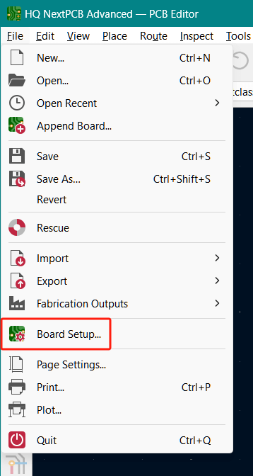
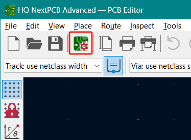
Board Setup in the KiCad main menu and toolbar
2. Click the Import Settings from Another Board... button on the bottom left of the new window.
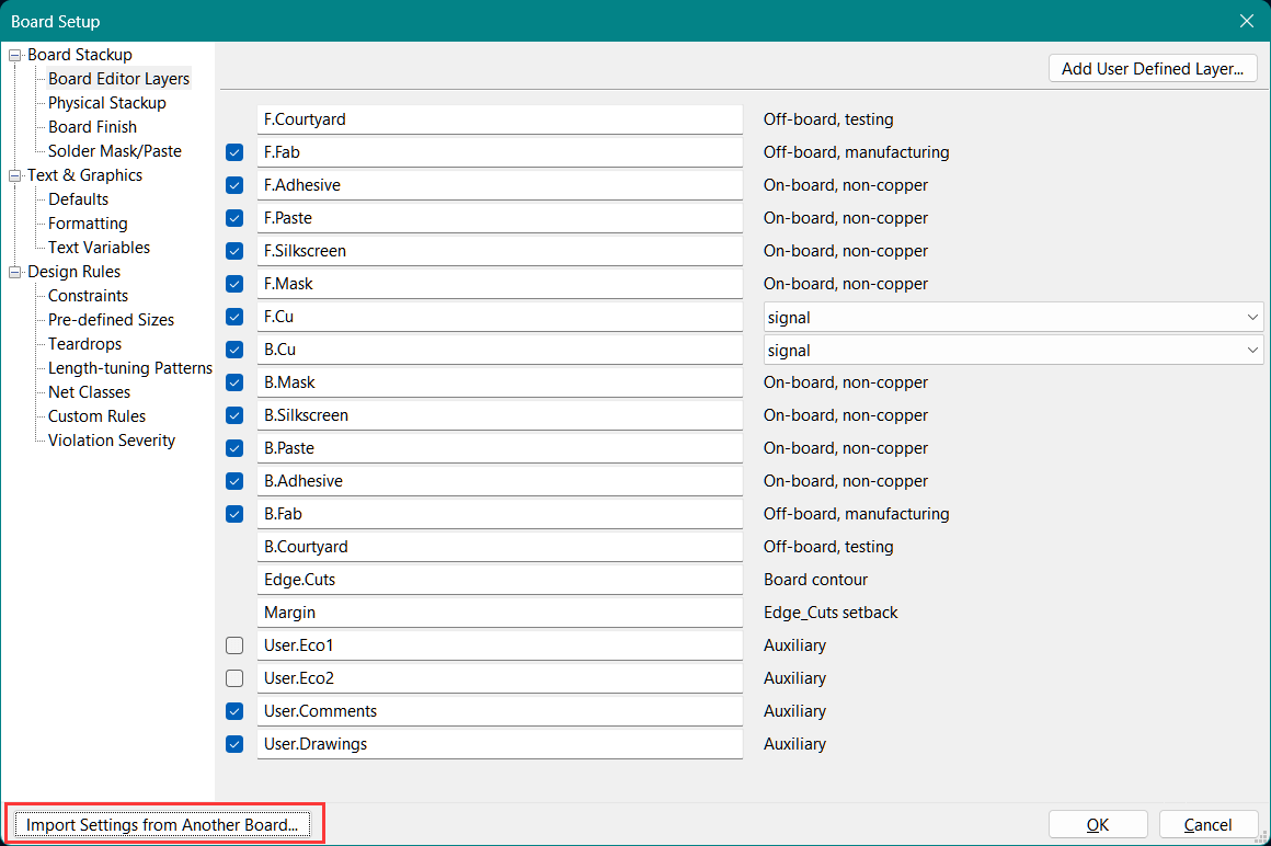
3. In the new window, choose the .kicad_pcb file that has the settings you wish to copy in the Import from: field. Below, you can pick and choose the specific settings to import. This is useful if you only need to copy over a few select settings. If you want to copy everything from the Board Setup menu, there is a Select All button on the bottom which will check all the boxes.
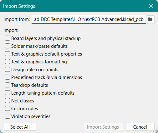
4. Then just click the Import Settings button and wait for KiCad to import the settings. Once successfully imported, the Import Settings and loading window will close. Confirm the new settings have been copied over and then click the OK button to close the setup and apply the changes.
We have provided two templates for HQ NextPCB's PCB manufacturing service. These settings are designed to help designers avoid manufacturing complications and unnecessary costs at the design stage which includes the DRC settings among other small modifications that are more compatible with our standard processes. Note that they are not mandatory to place orders with us and you are free to pick and choose which settings to import.
Currently, stackup settings are not supported due to complications preserving settings when switching layer counts.
Simple
Use the simple file settings for simple and cost-sensitive designs. These settings are designed to avoid additional manufacturing costs as much as possible within the scope of KiCad’s board settings and prefers suggested values over the limits of NextPCB’s manufacturing capabilities. This is suitable for most two and four layer designs.
Advanced
Use the advanced file settings for space-constrained and advanced designs that include fine-pitch components and high signal counts, for example. These are set to the limits of NextPCB’s manufacturing capabilities (within reason) as listed on the NextPCB website which could incur additional costs. This is suitable for complex multilayer designs. Notably, the allowed trace widths and drill holes are smaller.
Board Stackup: Some user layers removed for clarity. Too many additional layers can cause confusion, and important information is more likely to be overlooked. For multilayer boards, the inner layers have been renamed according to the total number of copper layers, where the first copper layer is the front copper layer. If this nomenclature is unfamiliar, feel free to ignore it.
6 layer board for example:
F.Cu -> F.Cu
In1.Cu -> GL2.Cu
In2.Cu -> GL3.Cu
In3.Cu -> GL4.Cu
In4.Cu -> GL5.Cu
B.Cu -> B.Cu
Text & Graphics: Changes to the silkscreen graphics and text default thickness.
Design Rules - Constraints: Values changed to best match HQ NextPCB’s production capabilities. The Simple file contains settings suitable for most basic designs. Follow these constraints if you want to avoid additional costs as much as possible. The Advanced version has the limits of our capabilities set for maximum freedom. More capabilities can be found here: https://www.nextpcb.com/pcb-capabilities
Pre-defined Sizes: We have provided a selection of pre-configured dimensions for your convenience. Most track widths are in mils for greater precision.
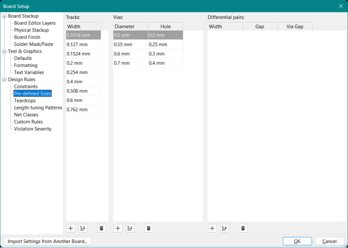
Net Classes: Small adjustments were made to the Net Classes.
Enjoy! For any questions or feedback, be sure to contact us at support@nextpcb.com
Founded in 2011, NextPCB is a leading industrial digital manufacturing platform for PCB manufacture, PCB assembly, components distribution, and electronics design verification tools. Their passion for reliable, fast and cost-effective electronics manufacturing services has transformed the industry, streamlining the entire production process and allowing production efficiency and cost-savings to reach record highs without compromising on reliability.
Serving national engineers for over 15 years, NextPCB has become a household name in providing full-feature multilayer PCBs and PCB assembly services engineers can trust. NextPCB brings these capabilities, speed, affordability and more to clients in over 160 countries.
Streamline Your PCB Design Workflow with KiCad Plugins from NextPCB
NextPCB Invigorates Partnership with KiCad Through Strategic Support and Innovation
Jumpstart Innovation with RP2040 and Free PCBA Prototypes
Save $200 on Professional Turnkey PCB Assembly from HQ NextPCB
Still, need help? Contact Us: support@nextpcb.com
Need a PCB or PCBA quote? Quote now