Support Team
Feedback:
support@nextpcb.com
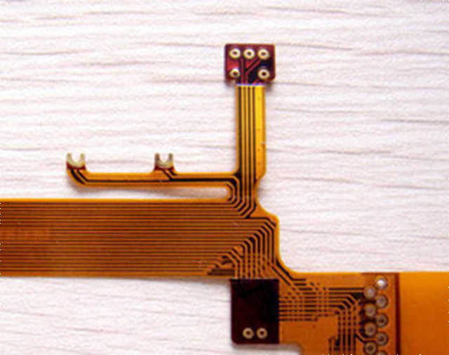
With the development towards miniaturization of products, flexible printed circuit boards (FPCs), with their advantages of being light, thin, and flexible, have been widely applied. However, compared to standard rigid boards, the design of flexible circuit boards is more challenging. Achieving the same electrical performance in such thin configurations is also difficult. Therefore, designing flexible circuit boards requires consideration of interconnect awakening, flexibility, reliability, and other structural needs, as well as the impact of material selection, processing methods, and manufacturing precision on the final product.
Flexible Printed Circuit Boards (FPCs), also known as flex circuits, consist of conductor circuits made on the surface of a flexible substrate, which may or may not include a cover layer. The dielectric constant of the flexible substrate medium is relatively low, providing good insulation and impedance performance to the conductors. At the same time, the flexible medium is thin and has flexibility, and it also has good tensile strength, multi-functionality, and heat dissipation performance.
Unlike standard PCBs (rigid boards), FPCs can be bent, folded, or repeatedly moved in many ways. To fully utilize the potential of FPCs, designers can use various structures to meet different needs, such as single-sided, double-sided, multilayer, and rigid-flex boards, among others.
Currently, there are two types of flexible boards on the market: printed (etched) and screen-printed. Screen-printed flexible boards, also known as Polymer Thick Film (PTF) flexible boards, differ from standard printed etching technology. PTF technology involves directly screen-printing conductive ink on the thin film medium as the conductor. Although the applications for PTF flexible boards are expanding (such as the popular membrane switches), printed flexible boards are still the most widely used of the two. This design specification focuses mainly on the structure and design methods of printed flexible circuits (Flexible Printed Circuit, FPC). The flexible boards mentioned in this specification refer to flexible printed circuit boards.
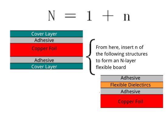
Typically, an N-layer flexible board is defined as a flexible board containing N layers of copper foil circuits, excluding conductive layers formed by screen printing, such as silver paste. For ease of explanation, if not considering the combination of substrate and medium, but only analyzing the cross-sectional view of the flexible board, an N-layer flexible board (N=n+1) can be represented by inserting n layers of copper foil laminated with glue and medium in the middle of a single-sided (1 layer) structure. When n=0, N=1, indicating a single-sided board. When n=1, N=2, indicating a double-sided board, and so on. The lamination structure is shown in the following diagram:
Note:
When there is a silver paste layer present, an additional silver paste layer and an adhesive cover film layer are added to the outermost part of the lamination structure shown in the diagram above.
In some cases, the surface cover film can be replaced with an ink solder resist layer, in which case the adhesive adjacent to the cover film may be omitted.
There are also some FPCs referred to as "pseudo-multilayer boards" or "segmented boards," where a layer of adhesive is missing between the copper foil layers, or there is adhesive only in certain areas. As a result, the copper foil layers are not fully laminated together but are separated. This design is also known as an "air cap" design.
As can be seen from the diagram above, the difference in the lamination structure between flexible boards and rigid boards is that the former includes an additional adhesive layer between the dielectric and the copper foil.
Of course, their biggest difference should be in the material characteristics used. Additionally, due to different materials and manufacturing processes, flexible boards can be made in odd numbers of layers, such as 3, 5 layers, etc.
In "air cap" designs, because there are fewer adhesive layers, the thickness of the single board is reduced, increasing the flexibility of the FPC. Moreover, the pseudo-multilayer approach can also reduce the number of layers processed for a single board, thereby reducing manufacturing costs. For example, sticking a single-sided copper-clad grounding board on the outside of a double-sided board as a shielding layer forms a pseudo-three-layer board.
In the design of flexible boards, the type and structure of materials are very important. They primarily determine the flexibility, electrical properties, and other mechanical characteristics of the flexible board: playing a significant role in the cost of the flexible board. All materials must be specified in the design drawings. To better illustrate, it is recommended to use cross-sectional schematic diagrams to represent the lamination structure of the flexible board.
Flexible copper-clad dielectrics and adhesive dielectric films available to FPC manufacturers should comply with IPC-MF-150, IPC-FC-231, and IPC-FC-232, or be in accordance with IPC-FC-241 and IPC-FC-232 specifications. These IPC specifications classify various materials according to their natural properties. The selection of suitable materials from a wide range must consider the following aspects:
Designers and FPC manufacturers must choose materials based on cost, performance, and manufacturability.
Depending on the requirements, different materials are used for flexible circuit boards. Considerations such as application scenarios and cost are taken into account. Common materials include Polyimide (with and without adhesive) and Polyester. The characteristics of these materials are compared in the following table:
|
|
Polyester |
Polyimide with adhesive |
Polyimide no adhesive |
|
|
|
|
|
|
Flexibility (radius approx. 2.0mm) |
Average |
Good |
Good |
|
Thermoforming |
Workable |
No |
No |
|
MODULUS |
2800MPa~5500 MPa |
2500MPa |
4000MPa |
|
Tear Strength |
800g |
500g |
500 |
|
Peel Strength (in air) |
1050N/M |
1750N/M |
1225N/M |
|
Chemical/Environmental Characteristics |
|
|
|
|
Etching (>20%) |
Advanced |
Poor |
Good |
|
UV |
PET:Poor |
Good |
Advanced |
|
UL Certification/Maximum Operating Temperature |
85*~165 |
85°~165* |
105*~200 |
|
Flame Retardant |
VTM-0 |
VTM-0 |
VTM-0 |
|
Electrical Properties |
|
|
|
|
Dielectric Constant (1MHz) |
3.4 |
3.5 |
3.3 |
|
Insulation Strength |
4-5KV/25μm |
3-5KV/25μm |
5KV/25μm |
|
Insulation Resistance |
10'g-cm |
10³g-cm |
10'g-cm |
|
Thermal Characteristics |
|
|
|
|
Soldering |
5 seconds @246°~260 |
5 seconds @288°(Requires pre-heat) |
5 seconds @288°(no need for pre-heat) |
|
Processing, Assembly Characteristics |
|
|
|
|
Through-hole Formation |
Limited |
Advanced |
Advanced |
|
Surface Mount (IR Reflow Soldering) |
PEN-Workable |
Good/Advanced |
Advanced |
|
Wire Bonding |
Poor |
Some adhesive workable |
Advanced |
|
Chip (Direct Adhesion) |
Poor |
Workable/Advanced |
Advanced |
Polyimide (PI for short) is the most commonly used thermosetting insulation material in flexible circuit processing. The thickness of the material typically ranges from 12.5μm (0.5mil) to 125μm (5mil), with some manufacturers offering thicknesses up to 7mil. The commonly used specifications are 25μm (1mil) and 12.5μm (0.5mil). Polyimide films, such as DuPont's "Kapton®" film, exhibit excellent flexibility, good dimensional stability, and can operate over a wide temperature range. Moreover, it is a flame-retardant material with outstanding resistance to soldering temperatures, maintaining its electrical performance under soldering conditions.
Polyester is made from polyethylene terephthalate (PET, polyethylene terephthalate) such as DuPont's "Mylar" film. Its thickness range for use in flexible boards is typically 25μm (1mil) to 125μm (5mil). It shares the excellent flexibility and electrical performance with Polyimide. However, its dimensional stability during the manufacturing process is slightly inferior to Polyimide. Additionally, its tear resistance is weaker, and it is more sensitive to soldering temperatures.
The choice of conductor materials for flexible boards mainly depends on the material performance under specific application conditions. Especially in dynamic uses, where the flexible board is continuously folded or stretched, a thin material with a long fatigue life is required. Typical conductors for flexible boards include copper foil, copper-nickel alloys, and conductive coatings.
The most common and economical conductor material in flexible boards is copper foil. Copper foil is mainly divided into electrolytic copper foil (ED, Electrodeposited copper) and rolled-annealed copper foil (RA, Rolled-Annealed copper).
Electrolytic copper is formed by electroplating. Its copper particles are crystallized in a vertical columnar structure, which is beneficial for creating vertical line edges during etching, aiding in the production of fine circuits. However, due to the columnar structure, it is prone to breakage when frequently bent. Rolled-annealed copper, the most used copper foil in flexible board manufacturing, has copper particles crystallized in a horizontal axis structure, making it more adaptable to repeated bending than electrolytic copper. However, because the surface of rolled copper is smoother, the adhesive side requires special treatment.
Besides copper foil, other conductor materials for flexible pcb boards include copper-nickel alloys (such as Constantan) and conductive coatings. Conductive coatings are pastes made from conductive materials (such as silver, carbon, etc.) mixed with polymeric adhesives (such as resin). The conductive coating is printed on the surface of the dielectric and then covered. For example, silver paste, if well insulated, can also have very good conductive performance. Compared to copper foil, conductive coatings have slightly inferior electrical performance and a higher impedance coefficient, making them unsuitable for use as conductors in some flexible applications.
Choosing the right adhesive to bond the conductor and the dielectric is also very important in the design of flexible boards. It must ensure that the FPC does not delaminate or excessively ooze adhesive during processing. Common adhesives used in flexible boards include acrylic, modified epoxy, phenolic butyrals, reinforced adhesive, pressure-sensitive adhesive, etc. The table below lists the characteristics of several adhesives.
|
Adhesive |
Peel |
Adhesive |
Moisture |
Surface |
Dissipation |
Dielectric |
|
Polyester |
N/A* |
10mils |
2.0 |
10⁴ |
0.02 |
4.0max |
|
Acrylic |
7.01b/in |
5mils |
6.0 |
10⁵ |
0.05 |
4.0max |
|
Epoxy |
8.01b/in |
5mils |
4.0 |
10⁴ |
0.06 |
4.0max |
|
Polyimide |
5.01b/in Min |
5mils Max |
3.0 |
105 |
0.010 |
4.0max
|
|
Butyral: Phenolic |
5.01b/in Min |
5mils Max |
2.0 |
104 |
0.025 |
3.0max
|
Acrylic adhesives and their modified versions are thermosetting materials. The material thickness generally ranges from 12.5μm (0.5mil) to 100μm (4mil), with 0.5mil and 1mil being the most common. They are widely used in high-temperature flexible applications (such as those requiring lead-tin soldering operations), ensuring no delamination or bubbling in these applications. They also have excellent chemical resistance properties, resisting the effects of chemicals and solvents during processing.
Unlike traditional acrylic adhesives, modified acrylic adhesives have some characteristics similar to thermoplastic materials. They are modified through partial lateral coupling. When the temperature exceeds their glass transition temperature (Tg), the adhesive sticks to copper or the dielectric. Due to the material's partial lateral coupling structure, the adhesive can be reapplied if necessary. Adhesives used in materials like Rogers' "R/Flex 2005" or DuPont's "Pyralux LF" are examples of modified acrylic adhesives.
Modified epoxy adhesives have a low coefficient of thermal expansion and are often used in multilayer flexible pcb boards or rigid-flex boards. Epoxy resin, a thermosetting material, is combined with other polymers to obtain modified epoxy adhesives with increased flexibility. They exhibit excellent properties in terms of Z-axis expansion, high adhesive strength, low moisture absorption rate, and resistance to chemical solvents during processing.
Phenolic butyrals, like Rogers' "R/Flex 10000" adhesive, are also thermosetting and share similar properties with epoxy resin. Additionally, they offer enhanced flexibility, making them more suitable for dynamic flexible applications. However, they cannot adhere polyimide dielectrics and epoxy adhesives.
Reinforced adhesives are created by infusing epoxy or polyimide resin into glass fiber. They are most commonly used for interlayer bonding in multilayer FPCs or rigid-flex boards.
The glass fiber infused with epoxy resin, also known as prepreg, can be used as an adhesive or as a base material film in rigid-flex boards. Unlike modified acrylic adhesives, its low coefficient of thermal expansion (CTE) and high glass transition temperature (Tg) significantly improve the Z-axis stability in multilayer FPCs.
The glass fiber infused with polyimide resin further increases the Z-axis stability of metallized holes in rigid-flex boards. Its CTE and Tg are even better than those of epoxy-infused ones, but it is more expensive and has a shorter lifespan.
Pressure-sensitive adhesives (PSAs) are perhaps the simplest and cheapest adhesives in FPC processing. As the name suggests, PSAs do not require a special lamination process and can be manually applied to the dielectric surface. However, due to their sensitivity to temperature and various chemicals, they are not suitable for bonding dielectrics and copper foil. Therefore, the main use of PSA is for attaching stiffeners or bonding rigid boards to flexible boards.
With the development of high-density FPCs, the demands for reliability and dimensional stability are increasing. Some major material suppliers, like DuPont and Nippon Steel, offer a type of material called adhesiveless laminates. Adhesiveless laminates address the issues related to adhesives in the production process (such as uneven adhesive thickness and oozing during lamination), and they also reduce thickness.
The cover layer is typically a lamination of dielectric film and adhesive or a coating on a flexible medium. Non-conductive films or coatings can be selectively applied to the surface of FPCs to protect against contamination, moisture, scratches, etc. Common protective layers include cover film and solder mask.
Cover film is a lamination of dielectric film and adhesive. The adhesive used is the same as introduced before, typically with a thickness of 25μm. There are also adhesiveless cover film materials. The dielectric film and substrate medium mainly include two types:
Polyimide, with thicknesses generally ranging from 25μm, 50μm to 125μm. Its properties, as introduced for the substrate medium, mainly include good flexibility and high-temperature resistance.
Polyester, with thicknesses generally ranging from 25μm/50μm/75μm. Its properties, as introduced for the substrate medium, mainly include being relatively inexpensive, good flexibility, but not high-temperature resistant.
In certain applications, flexible pcb boards can use solder mask ink for conductor protection and insulation, just like standard rigid boards. The ink is available in a variety of colors to suit different environments. For instance, flexible boards connected to cameras use black ink to prevent reflection. Additionally, ink is inexpensive and can be processed through printing, making the overall cost very low. However, its flexibility is not as high as that of cover film.
Advantages: Good bending performance; thicker, offering higher protection and insulation strength.
Disadvantages: Cover film with adhesive may ooze adhesive when laminated, not suitable for small pads. Solder mask windows are generally created through drilling; achieving right angles or square windows requires additional tooling or methods like laser cutting, which are more challenging. The overall cost is relatively high.
Advantages: Thin, suitable for applications requiring thinness and not very high flexibility. Available in a variety of colors. Processed through printing, simple. No adhesive oozing, suitable for fine pitch pads. Overall cost is low (a quarter or less than the cost of PI cover film).
Disadvantages: Because it is thinner, its insulation strength is not as high as PI cover film. Poor bending performance, generally less than 10,000 times, not suitable for applications with high dynamic requirements.
In many applications, such as device soldering, flexible boards require stiffeners (also called reinforcement plates) for external support. Stiffener materials include PI or Polyester films, glass fiber, polymer materials, steel sheets, aluminum sheets, etc.
PI or Polyester films are commonly used materials for flexible board stiffeners. The common thickness is 125μm (5mil), providing some rigidity.
Glass fiber (such as FR4) is also a commonly used stiffener material. The rigidity of glass fiber stiffeners is higher than that of PI or Polyester, used where higher rigidity is required. The thickness generally ranges from 125μm (5mil) to 3.175mm (125mil). However, its processing is more challenging compared to PI, and it may not be a standard material available to some flexible board manufacturers.
Polymers (Polyetherimide), such as plastics, have a low water absorption rate, and are resistant to high pressure and high temperatures.
Steel sheets, aluminum sheets offer high support rigidity and can also dissipate heat. Rigidity or heat dissipation in the design are the main concerns.
The line width, copper thickness, and via size of flexible boards should prioritize their current-carrying capacity. The current-carrying capacity is also related to the application environment, cooling conditions, and allowable temperature rise. The commonly used copper foil thicknesses in FPCs are 0.5oz and 1.0oz, with common design line widths ranging from 4mil to 10mil. For their maximum current-carrying capacity with an allowable temperature rise of 10°C, please refer to the following table (calculated according to the IPC-D-275 standard):
|
Table of current carrying capacity for trace widths of 0.5oz and 1.0oz copper thickness |
|
||||||||||
|
Trace Width(mil) |
|
|
|
|
|
|
|
|
|
||
|
0.50z |
10°C Temperature Rise Current (A) |
0.342 |
0.397 |
0.449 |
0.498 |
0.545 |
0.59 |
0.633 |
0.941 |
1.267 |
|
|
1.0oz |
10°C Temperature Rise Current (A) |
0.545 |
0.663 |
0.716 |
0.794 |
0.869 |
0.941 |
1.01 |
1.5 |
2.0 |
|
|
DC Voltage Drop (mV/inch) at this Current |
70.2 |
65.2 |
61.5 |
58.4 |
55.9 |
53.8 |
52.0 |
42.9 |
37.3 |
||
Material: SYTECH
Layer Count: 4 layers
PCB Thickness: 1.6mm
Min. Trace / Space Outer: 0.1mm/0.1mm
Min. Drilled Hole: 0.2mm
Via Process: Tenting Vias
Surface Finish: ENIG+OSP
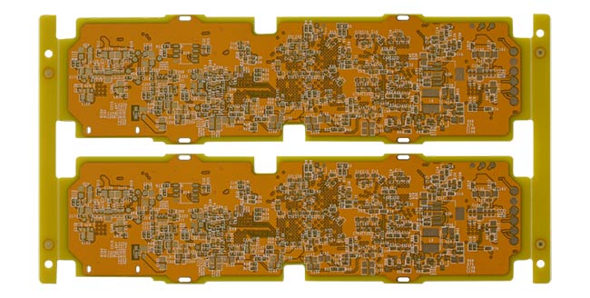
Material: Fr-4
Layer Count: 4 layers
PCB Thickness: 1.4mm
Min. Trace / Space Outer: 0.065mm
Min. Drilled Hole: 0.2mm
Via Process: Tenting Vias
Surface Finish: ENIG
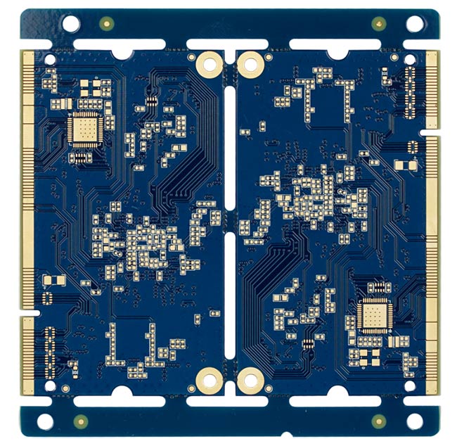
Material: Fr-4
Layer Count: 6 layers
PCB Thickness: 1.6mm
Min. Trace / Space Outer: 3/3mil
Min. Drilled Hole: 0.25mm
Via Process: Tenting Vias
Surface Finish: ENIG
PCB is the abbreviation of the...


