Contact Us
Blog >> Blog Details Page

Home Automation System Using ESP32

Posted:11:10 AM December 21, 2023 writer: The Engineering Projects

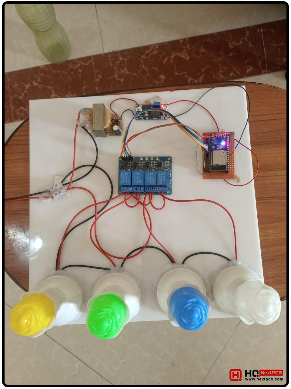
Hello students! Welcome to a new tutorial on the ESP32 microcontroller board. In this era of technology, where everything is becoming more automated, a home automation system is considered one of the most frequently designed projects in the Internet of Things(IoT) world. Today, we are presenting a simple home automation project using the ESP32, where the user can control four bulbs remotely. For demonstration, we have used simple bulbs but the scope of the project goes beyond this. We can control home appliances with ESP32 using the same procedure. This project is not only useful in daily household life but it is also considered one of the most appropriate projects for students who are searching for projects related to circuits, microcontrollers, the Internet of Things, or embedded systems. 

In this tutorial, we’ll start with a detailed description of the project and understand the workings of each basic component. After that, we’ll see the code and study it thoroughly for clear concepts. We’ll see all the material required for this project and the step-by-step procedure to complete it. Let’s start with the project description.

Home Automation Project Description

  • The heart of this project is ESP322, which can be connected to devices (mobiles or computers) remotely over the internet.
  • At the end of this project, four bulbs are used to check the output at every pin. 
  • The user can see four buttons on their device and can turn on/off any of the bulbs through these buttons. 
  • The power of 220 V is applied to the circuit through the switch.
  • The current passes through the transformer>diodes>buck converter> ESP32> Relay> and bulbs.
  • At every point, the voltage and current type change according to the needs of the component. Using these additional components guarantees the safety and functionality of the project. 
  • The appliances are controlled through the setting of the pins specified in the code. 
  • The ESP32 can control multiple devices at a time and users can control all the appliances simultaneously. 

Working on Components in Home Automation Project

Before starting the preparation for the project, it is important to understand the workings of each component. Each one of these has a specific duty and it is important to include all of them in the project. Here are the main components of the home automation project:

Transformer

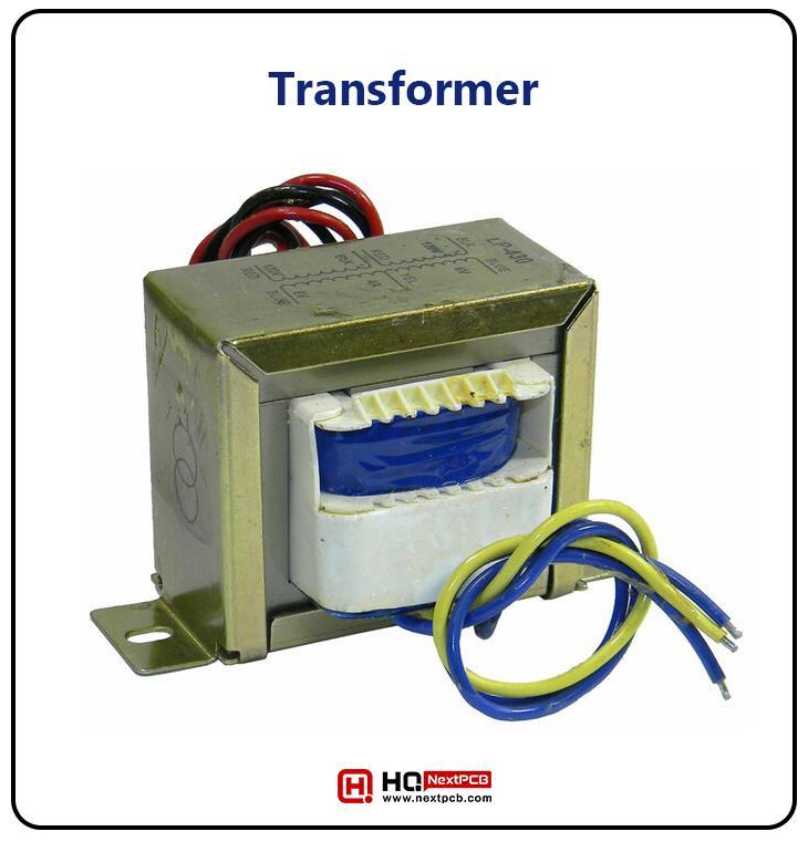
A transformer is used to change the voltage level of its input. There are different types of transformers that are: 

  • General purpose transformers
  • Industrial control transformers
  • Isolation transformers
  • Medium voltage control transformers
  • Military transformers
  • Step up transformer
  • Step down transformer
  • Power transformers

Out of these, we are only interested in the working of a step-down transformer. It is defined as:


“A step-down transformer is a device that reduces the voltage level from its input to the output.”

It is a highly efficient device that is used in multiple home appliances and is one of the basic components of home automation projects.

Get Instant Online Quote

Here are some of the functions of the step-down transformer in this project:

  • In the home automation project we are using, different components are used that run on their specific voltage levels. The main power supply in the house is 220V. The step-down transformer converts this 220V AC to 12V AC. So here, the transformer is used for the power supply adjustments. The optimal voltage supply is important for the compatibility and performance of the devices in the circuit. 
  • The safety of the components requires the appropriate voltage. All devices are not the same in the home automation system. The sensors, microcontrollers, output devices, etc. have different sensitivities in the circuit and providing a steady and appropriate level of voltage is necessary. 
  • The power waste is another big reason behind using the transformer in the circuit. The excess power is not only harmful to the circuit but is also a waste of resources. Home automation systems can be extended on a very large scale. There, extra usage of the power creates a lot of burden. 

Diodes with Transformer

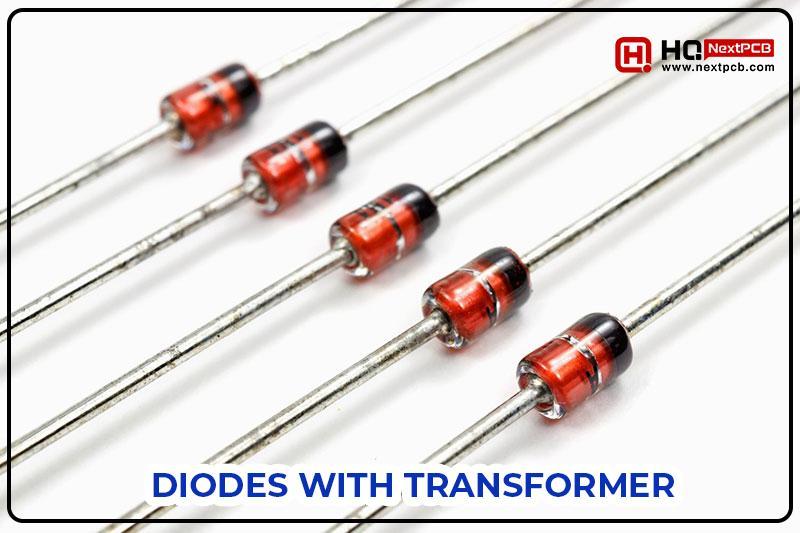
Till now, we have seen the conversion of the voltage level but we know that the electronic components we are using here use direct current (DC). There are four diodes used in this project to convert the AC into DC. Hence, the wires connected to the input of the transformer have 20 volts of AC, whereas the wires connecting to the output of these diodes have 12 volts of AC. This is important because the components coming next run on DC. 

Buck Converter in Home Automation

A buck converter also acts like a step-down transformer but there are some differences here. This device takes the rectified current, which is direct current (DC). It further lowers the voltage level to make it appropriate for the ESP32. In home automation projects, a buck converter is often seen before the microcontroller because these devices require a steady and stable voltage level with the least fluctuation. Here are some important points about its structure:

  • A buck converter has a transistor in its structure (usually a MOSFET) that acts as a switch and mainly has the feature of controlling the current flow through the buck converter. 

  • It has an inductor that stores the magnetic field during the “on” period and releases this energy during the “off” state of the converter. As a result, fewer fluctuations in the electric field are obtained. 
  • The buck converter also has a diode in it, which is used to cut off any access to the AC loop. We know that diodes cannot rectify the current waves ideally; hence, in the case of the previous diodes having some part of AC, this diode provides a smooth DC.

ESP32 in Home Automation

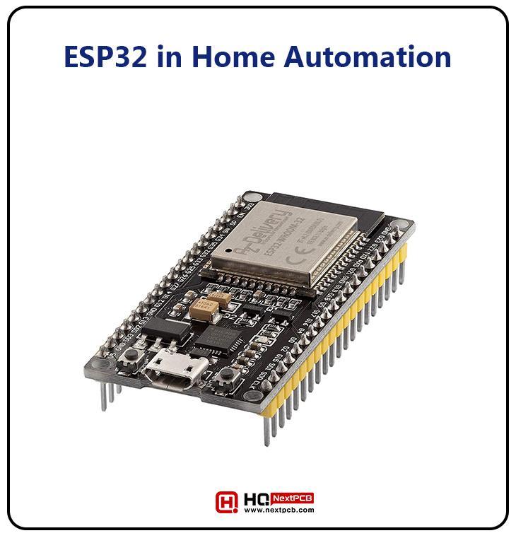
The ESP32 is a microcontroller that acts as the heart of this project. This is one of the most popular choices for home automation and other Internet of Things (IoT) projects. It is because it is versatile, low cost, and has the robust capabilities to handle a great number of components working together. It has multiple features for wireless connectivity, such as WiFi and Bluetooth, that make it ideal for the home automation system because it can virtually connect and control these devices. Here is the working of this microcontroller in the project we are discussing:

  • The ESP32 is controlled with the help of programming in C++. It has 48 pins (digital and analogue) which is the reason behind the versatility of the ESP32. 
  • The ESP32 is programmed in a lightweight IDE called Arduino IDE. Here, simple code is enough to provide the commands on different pins. 

  • The pins connect with the external component, which, after receiving the electricity in the form of signals, is turned on/off according to the commands of ESP32. 
  • There are some features of ESP32 that allow it to be programmed without any physical connection with the system, such as Over the Air (OTA) programming. This is a big relief for home automation projects. 
  • In this project, the ESP32 can control four relays, which means it can be used to control four devices at a time. 
  • We program the ESP32 in Arduino IDE and get the IP address. Once the address is run on the device in the network, the user can simply turn on/off the devices with the device. 

Relay in the Home Automation Project

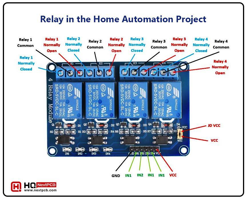
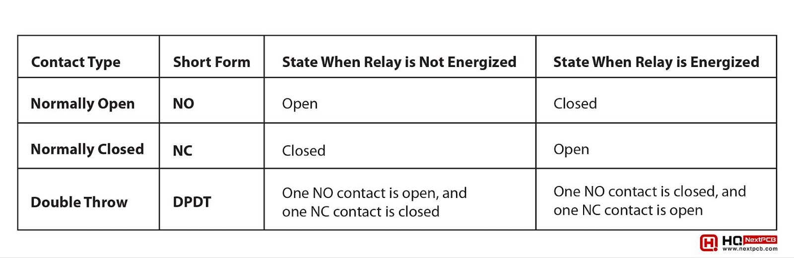
A relay is an electromechanical switch used in circuits to control the flow of electricity in them. Till now, the ESP32 has 5V AC but this cannot be fed into the bulbs directly. To convert it into the bulb user form, we require 220V AC. This may be confusing for you but the components we have used till now in this circuit are only to make the voltage compatible with the ESP32. Yet, there is a need to regain the real voltage values to use them with the final components of the system. Moreover, the relay also acts as a protecting device for the ESP32 because it stops the back EMF from reaching the ESP32. 

  • It is used to control the high-power circuit with the low-power signal. The component of its body is an electromagnet, which is a coil of wire wrapped around the softcore. When current, coming from ESP32, passes through it, an electromagnet field is generated that attracts its armature. 
  • The armature is responsible for opening/closing the circuit according to the stream of current coming from the ESP32. 
  • The relay has some conducting elements called contacts that play a role in passing the current according to the stream. Here are the states and workings of these contacts in different situations:


Contact Type

Short Form

State When Relay is Not Energized

State When Relay is Energized

Normally Open 

NO

Open

Closed

Normally Closed 

NC

Closed

Open

Double Throw 

DPDT

One NO contact is open, and one NC contact is closed

One NO contact is closed, and one NC contact is open
 

Get Instant Online Quote

  • A spring is attached to the relay that allows it to easily open or close due to the electromagnetic field. 
  • When any of the components are turned on/off during the experiment, these relays create a sound because of the opening or closing of these contacts. 

Bulbs in the Home Automation Project

At the end of this circuit, the current passes to the bulb. These are controlled by the user through the browser connected to the network. The important thing to notice here is that we are using bulbs for easy representation of the circuit. Any component that can be run on AC power, such as fans, can be controlled through the project. In such a case, the circuit will not be as clear and open as it is given here in this project. 

Code for Home Automation Project using ESP32

The whole project is controlled with the help of code in ESP32. The outputs on the pins of ESP32 and the interface to control the bulbs are specified in the code. Here is the whole code that simply specifies the information for the user and the ESP32:

// Load Wi-Fi library

#include


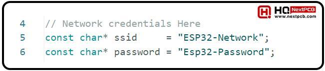
// Network credentials Here

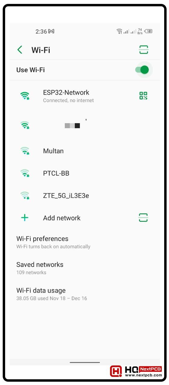
const char* ssid     = "ESP32-Network";

const char* password = "Esp32-Password";


// Set web server port number to 80

WiFiServer server(80);


// Variable to store the HTTP request

String header;


//variables to store the current LED states

String statePin16 = "off";

String statePin17 = "off";

String statePin4 = "off";

String statePin5 = "off";

//Output variable to GPIO pins

const int ledPin16 = 16;

const int ledPin17 = 17;

const int ledPin4 = 4;

const int ledPin5 = 5;

// Current time

unsigned long currentTime = millis();

// Previous time

unsigned long previousTime = 0;

// Define timeout time in milliseconds

const long timeoutTime = 2000;


void setup() {

  Serial.begin(115200);


  pinMode(ledPin16, OUTPUT);      // set the LED pin mode

  digitalWrite(ledPin16, 0);      // turn LED off by default

  pinMode(ledPin17, OUTPUT);      // set the LED pin mode

  digitalWrite(ledPin17, 0);      // turn LED off by default

   pinMode(ledPin4, OUTPUT);      // set the LED pin mode

  digitalWrite(ledPin4, 0);      // turn LED off by default

  pinMode(ledPin5, OUTPUT);      // set the LED pin mode

  digitalWrite(ledPin5, 0);      // turn LED off by default

  WiFi.softAP(ssid,password);


  // Print IP address and start web server

  Serial.println("");

  Serial.println("IP address: ");

  Serial.println(WiFi.softAPIP());

  server.begin();

}


void loop() {

  WiFiClient client = server.available();   // Listen for incoming clients


  if (client) {                             // If a new client connects,

    currentTime = millis();

    previousTime = currentTime;

    Serial.println("New Client.");          // print a message out in the serial port

    String currentLine = "";                // make a String to hold incoming data from the client


    while (client.connected() && currentTime - previousTime <= timeoutTime) {

      // loop while the client's connected

      currentTime = millis();

      if (client.available()) {             // if there's bytes to read from the client,

        char c = client.read();             // read a byte, then

        Serial.write(c);                    // print it out the serial monitor

        header += c;

        if (c == '\n') {                    // if the byte is a newline character

          // if the current line is blank, you got two newline characters in a row.

          // that's the end of the client HTTP request, so send a response:

          if (currentLine.length() == 0) {

            // HTTP headers always start with a response code (e.g. HTTP/1.1 200 OK)

            // and a content-type so the client knows what's coming, then a blank line:

            client.println("HTTP/1.1 200 OK");

            client.println("Content-type:text/html");

            client.println("Connection: close");

            client.println();


            // turns the GPIOs on and off

            if (header.indexOf("GET /16/on") >= 0) {

              statePin16 = "on";

              digitalWrite(ledPin16, HIGH);               // turns the LED on

            } else if (header.indexOf("GET /16/off") >= 0) {

              statePin16 = "off";

              digitalWrite(ledPin16, LOW);                //turns the LED off

            }


            if (header.indexOf("GET /17/on") >= 0) {

              statePin17 = "on";

              digitalWrite(ledPin17, HIGH);               // turns the LED on

            } else if (header.indexOf("GET /17/off") >= 0) {

              statePin17 = "off";

              digitalWrite(ledPin17, LOW);                //turns the LED off

            }

            if (header.indexOf("GET /4/on") >= 0) {

              statePin4 = "on";

              digitalWrite(ledPin4, HIGH);               // turns the LED on

            } else if (header.indexOf("GET /4/off") >= 0) {

              statePin4 = "off";

              digitalWrite(ledPin4, LOW);                //turns the LED off

            }

            if (header.indexOf("GET /5/on") >= 0) {

              statePin5 = "on";

              digitalWrite(ledPin5, HIGH);               // turns the LED on

            } else if (header.indexOf("GET /5/off") >= 0) {

              statePin5 = "off";

              digitalWrite(ledPin5, LOW);                //turns the LED off

            }

            // Display the HTML web page

            client.println(" ");

            client.println(" ");

client.println(" ");

            // CSS to style the on/off buttons

            client.println(" ");

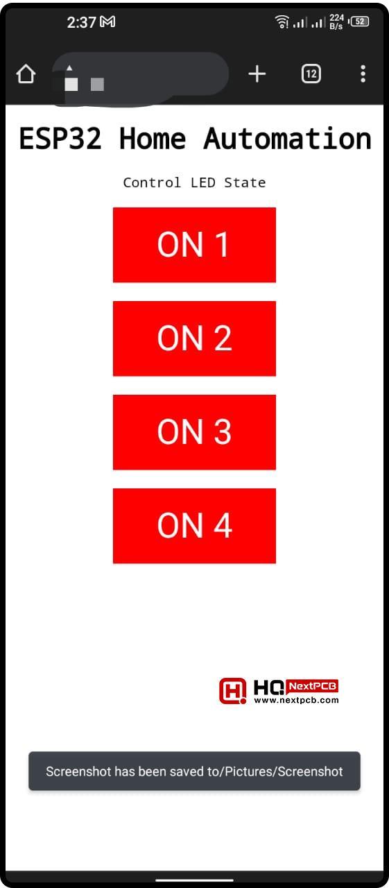
            client.println("ESP32 Home Automation");

            client.println("Control LED State");

            // Display the HTML web page

            client.println(" ");

            client.println(" ");

            client.println(" ");

            // CSS to style the on/off buttons

            client.println(" ");

            if (statePin16 == "off") {

              client.println("ON1");

            } else {

              client.println("OFF1");

            }

            if (statePin17 == "off") {

              client.println("ON2");

            } else {

              client.println("OFF2");

            }

            if (statePin4 == "off") {

               client.println("ON3");

            } else {

               client.println("OFF3");

            }

            if (statePin5 == "off") {

               client.println("ON4");

            } else {

             client.println("OFF4");

            }

            client.println("");

            // The HTTP response ends with another blank line

            client.println();

            // Break out of the while loop

            break;

          } else { // if you got a newline, then clear currentLine

            currentLine = "";

          }

        } else if (c != '\r') {  // if you got anything else but a carriage return character,

          currentLine += c;      // add it to the end of the currentLine

        }

      }

    }

    // Clear the header variable

    header = "";

    // Close the connection

    client.stop();

    Serial.println("Client disconnected.");

    Serial.println("");

  }

}

Get Free PCB Assembly

Code Explanation for Home Automation Project

For better understanding, we are dividing the code into different parts. Once you have understood the code in detail, you will understand the workings of each component in detail:

Including the Library

The first step is to include the library in the code. This library has built-in functions and other necessary information that we can use for the best functioning of the project. 

Setting the code Variables

In the next step, we’ll set some special variables that we’ll use throughout the code. Here is an explanation of each step:

  • First of all, we’ll set the credentials for the Esp32. For this, we have declared the variable “character” and stored the name of the network and the password for it.
  • The built-in function of the library is used to initiate the server. This server is required to provide the space to use the interface to control the components. Here, we are using port 80 for this purpose. 
  • The string header specifies the protocol used for the interface. We are using HTTP for safe communication between the system and the ESP32. 
  • In this project, four bulbs are controlled; therefore, we are specifying four variables for the pins. For convenience, we have specified the names according to the ESP32’s pins. Here, we are specifying the current state of the pins and initially, these are kept off. These are the states of the pins; therefore, we have used the string data type here. 
  • In the next step, we are assigning a number to the physical pins of the ESP32. We’ll use it in the code next. 
  • Information like the current time and the unit of the time are also specified in this part. 

Void setup() 

The setup function is the one where the main body of the code starts. This is the part of the code that will run only once when the user hits the compile button. 

  • Here, the baud rate is specified in the first line. We are using the baud of 115200 for the serial monitor. 
  • After that, the variables specified in the previous section are used. We are considering these pins as output here. For this, we have used the built-in function “pinMode” here.
  • These pins are then assigned the value 0 with the “digitalWrite” function. Hence, initially, the pins are kept close. 
  • In the next step, the other built-in function is used so the ESP32 can be used as an access point with all these settings. 
  • The specifications of the serial monitor are shown here. The function is used to get the IP address of the ESP32. For this, we are using the serial print function. 

Void loop () 

The void loop is checked again and again in the code when it is executed. Here are the steps performed in this part of the code:

  • The requests to the clients are executed here. For this, we have used the function where we are checking if the server is responding or not. In the previous section, we turned the server on. Here, we specify that if the server is available, then the client is initiated. 
  • The first “if loop” checks if the client is initiated. If yes, then it shows the message on the serial monitor. This setting helps us identify any issue in the connection if it is not working. 
  • The while () loop checks for the state of the client at a specific time. Here, the values of variables such as the current time and the previous time are used. The bytes are read from the client and the output is generated accordingly. 
  • The output of the serial port is printed according to the current status of the client. 
  • To turn the bulbs on and off according to the user’s request, the if-else loop is used. Whenever the user turns any input high through the button, the GPOI pins act accordingly and as a result, the output is generated. 

HTML Web Page Interface 

Here, simple HTML code is used to make things more attractive and user-friendly. At every point, the client function is used to print the details of all the things happening on the HTML page. 

For the appealing interface, CSS is used. We need four buttons to handle the functionality of four bulbs. The labels and the functionality match here. The if-else loops match the state of the button and the output at the GPOI pins. In the end, the stop function is used by the client to stop the working of anything in the code. This is called when the user does not do anything and there is no web page interface. At this point, anything turned on/off in the system remains in its current situation and if the user wants to change something, he has to be connected to the network again. 

Getting Started with the Home Automation Project

Now that we know the workings of all the important components of the project, we can move on to the practical implementation and construction of the project. Let’s start with the materials used in the project and after that, we’ll see the procedure in detail. 

Component Required

  • ESP32 micorcontroller
  • Relays (4)
  • Step down transformer 
  • Buck converter
  • Bulbs (4)
  • Diodes (4)
  • Bulb holders
  • screws
  • Connecting wire
  • Connecting tape
  • Glue
  • Switch
  • A piece of board
  • Internet connection
  • BroswerComputer system
  • Arduino IDE

Procedure

The experiments involving microcontrollers consist of two basic parts: preparing the software as well as the hardware. Let’s start with the software part.

Setting the ESP32 in Arduino IDE

  • Open your Arduino IDE on the system.
  • Connect the ESP32 to it with the help of a USB cable.
  • Create a new project for it. Make sure you have installed the right port and board on your Arduino IDE. 
  • Delete the existing code from the project and paste the one given in this article. 
  • Check the whole code to see if there are any errors. 
  • I have set the name and password of the ESP32 as given in the following image for my convenience:

  • You can change these credentials by making changes in the string part if required. 
  • Run the code by clicking on the verify button in the upper left corner of the screen. 
  • Click on the upload button to save this code to the ESP32. It will again show the loading on the console.
  • Once the loading is complete, click on the “Boot” button on the ESP32 to fully upload the code. 

Getting the IP Adress of ESP32 at Arduino IDE

Once the code is loaded successfully, we need the IP address specific to the ESP32 to get the interface of the experiment.

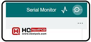
Go to the serial monitor from the upper right corner of the screen:

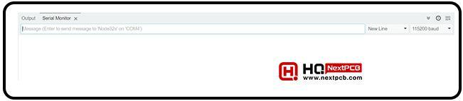
Right now, it does not show any output. Click on the EN button on the ESP32 to get the output.

  • The step-by-step loading of this code will show you the success of the code. In the end, you will see the IP address of the ESP32. Copy this address. The interface to control the bulbs is present at this IP address. 

  • Open the wifi networks of the device through which you want to control the bulbs. In my case, I will do it on my mobile phone.
  • There, you will see the name of the wifi network as named in the code. Try to connect with it.
  • Use the password that you have specified in the code. In this way, the mobile is now connected to the WiFi signals of the ESP32.

Now that we know that ESP32 is working fine, we can move on to the hardware formation of the project. To do this, you have to plug the ESP32 out of the system. Don’t worry, because if the ESP32 was running fine at this point, it will work best with the project as well and you can reconnect it later. 

Setting the Home Automation Project 

  • Get a flat board to set all the components on it.
  • Place all the basic components on it according to the sequence given here:
    transformer>diodes>Buck converter>ESP32>Relay>Connection to the bulb.
  • Use the tapes to place the objects in their places. 
  • Connect all these with the help of connecting wires. The project must look like the following image:

  • Use the glue to make sure a secure and safe connection is made to each component. 
  • If you have followed all the instructions, the hardware is ready to run. 

Checking the Home Automation Project using ESP32

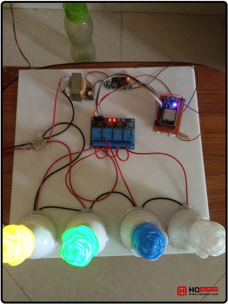
If all the steps given above are complete, then the project is now ready to be used. Here are the steps to check if it is working fine:

  • Power up your projects by using the switch you have attached at the start of the project. 
  • The lights on the ESP32 will indicate that the project is getting power. 
  • From the mobile, check for the wifi connections. You will see the ESP32 there. Try to connect with it.
  • Enter the password you have mentioned in the code and connect the mobile device to ESP32. 

  • Now, from the same device, go to any browser you are using.
  • Type the IP address that we have obtained in our previous steps in this project. 
  • Here, you will see the following interface:


Controlling the Home Automation Bulbs through Mobile Interface

  • Each button in the interface is connected to a specific bulb. Let us change the state of the bulb through the buttons to get the required functionality. 
  • Click on the button of the bulb you want to open/close. 
  • Every time there is a change in the state of the bulb, the relay makes a sound. It is because of the change in the electromagnet that the size of the armature of relays changed. 
  • At this point, the project is used to control the bulbs for an easy demonstration. This can be extended to other home appliances. 
  • Every time you change the output, the lights on the relay are changed accordingly.

Get Free PCB Assembly

Output of Home Automation Project

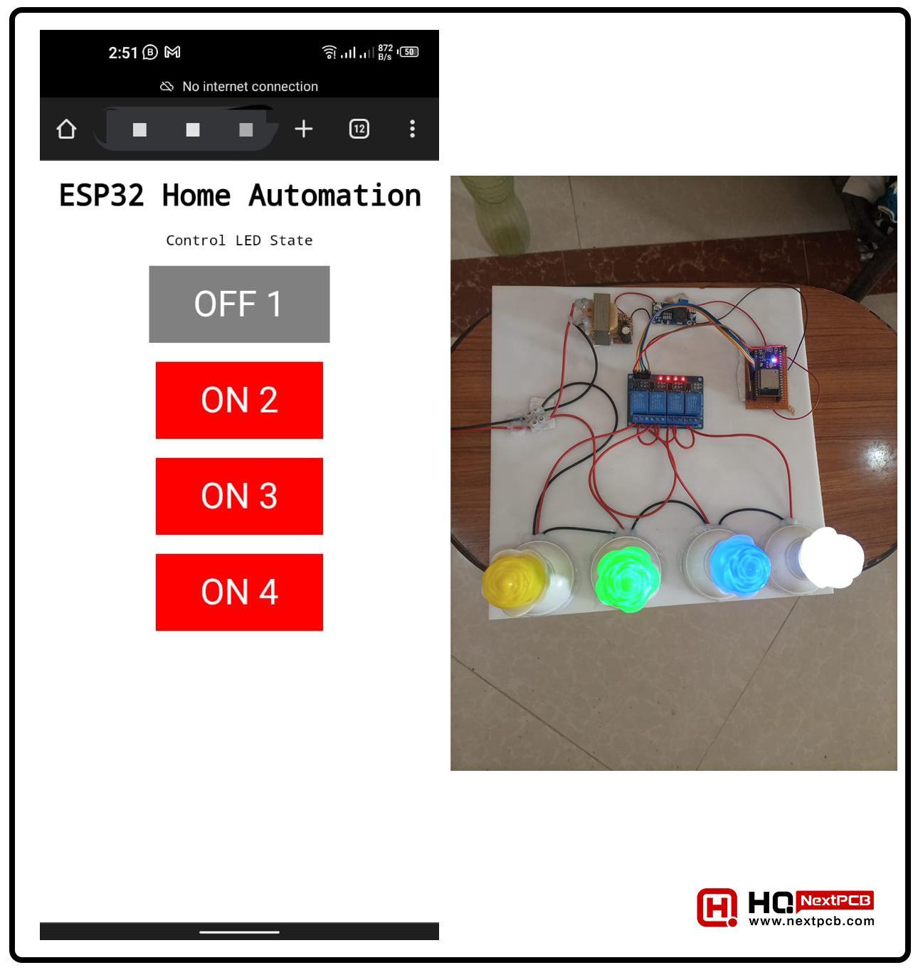
Now, we’ll control the state of the bulbs remotely through the interface we have just shown you. Here is the output when all the bulbs are turned on through the website interface:

Now, when the first light is turned off, the following output is shown:

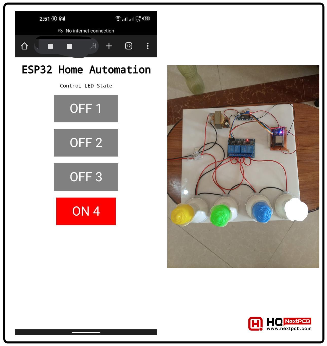
When two lights are turned off, the following output is seen:

Similarly, the output for three lights is shown in the following way:


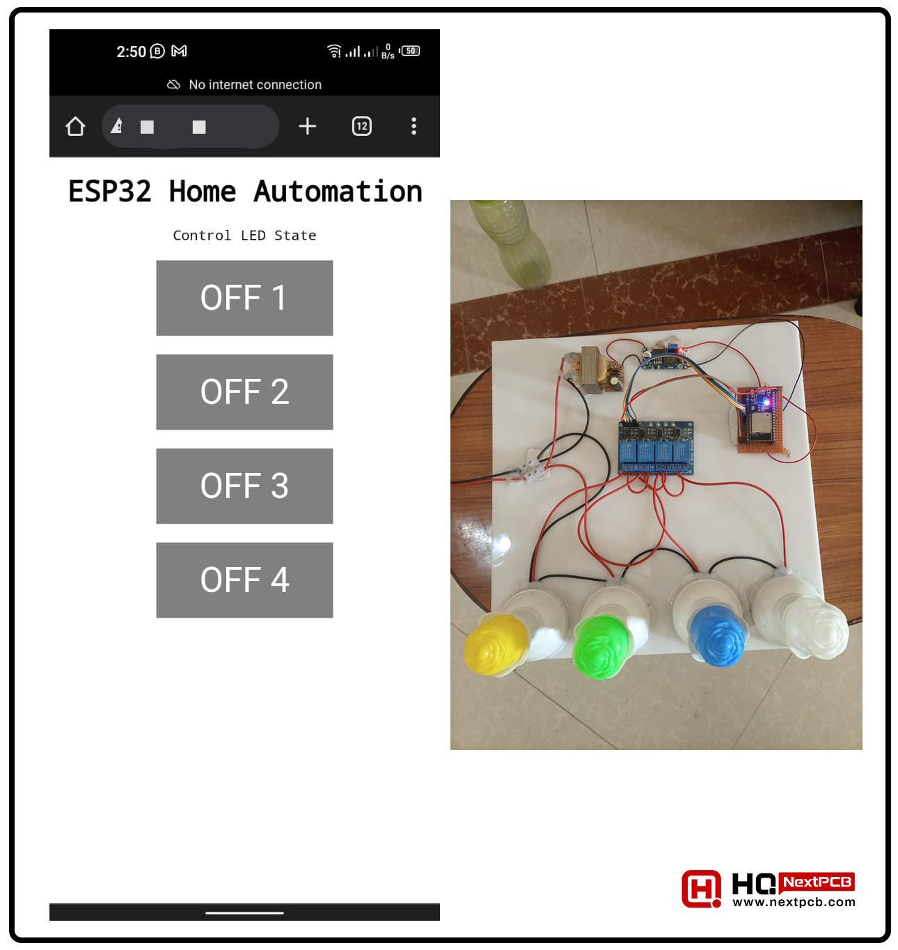
When all the lights are turned off, the results are as expected:

Precautions to Use the Project

  • Here are some important points to keep in mind when dealing with this project:
    Don’t touch the components when the power of the project is on. 
  • Make sure you have installed the right board and are using the right port in the Arduino IDE.
  • Connect the components with the right connection; otherwise, the project will not run.
  • Make sure the components are getting the right amount of electricity.
  • Always check for the power in the component and then connect it to the project. 
  • Make sure you are using the right password and network settings

Hence, in this way, we have created a project in which we are controlling four bulbs at a time with the help of ESP32. The user can control the state of the bulbs through their mobile device or any other device that has a browser. We started with a simple project description and studied all the basic components and their workings. After that, we have seen the code and its details to understand the concepts. In the next step, we saw all the points by following which, we can set the hardware part of this project. This is the best example of using the basic components to show the working of ESP32. I hope your project is running well because I have tried my level best to explain each point in detail. Still, if you are facing any issues, you can ask in the comment section. 

You may also be interested in...

ESP32 BLE(Bluetooth Low Energy) Control in Arduino IDE

Getting Started with ESP32

Free Worldwide Shipping on Over 600,000 Electronics Components with HQ Online

Free PCB Assembly Offer is Now Live: Experience Reliable PCB Assembly from HQ NextPCB

HQ NextPCB Introduces New PCB Gerber Viewer: HQDFM Online Lite Edition

  • PCB
    Prototype
  • PCB
    Assembly
  • SMD
    Stencil

Dimensions: (mm)

×

Quantity: (pcs)

5
5
10
15
20
25
30
40
50
75
100
120
150
200
250
300
350
400
450
500
600
700
800
900
1000
1500
2000
2500
3000
3500
4000
4500
5000
5500
6000
6500
7000
7500
8000
9000
10000

Other Quantities:(quantity*length*width is greater than 10㎡)

OK

Layers:

Thickness:

Quote now