
 NextPCB Capabilities
Printed Circuit Boards
NextPCB Capabilities
Printed Circuit Boards
 PCB Assembly
 Layer Buildup
 SMD-Stencils
 PCB Design-Aid & Layout
 Mechanics
 Quality
 Drills & Throughplating
 Factory & Certificate
 PCB Assembly Factory Show
Certificate
PCB Assembly Factory Show
Certificate
Support Team
Feedback:
support@nextpcb.com


Potentiometers (often called "pots") are indispensable variable resistors in electronics, enabling precise control over electrical current or voltage within a circuit. Even as digital interfaces dominate new product development in 2026, mechanical potentiometers remain critical for tactile user interfaces, real-time analog calibration, and robust industrial controls.
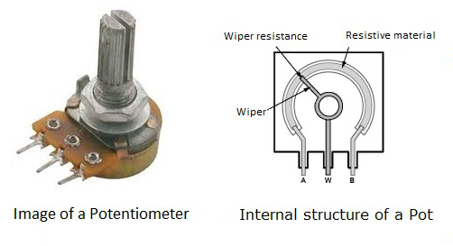
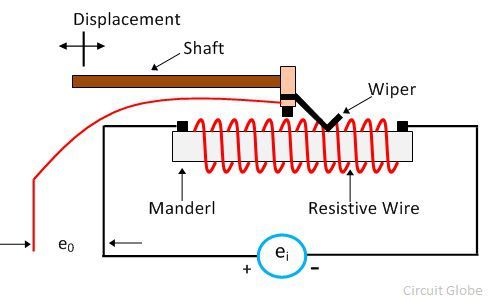
Constructed from resistive materials like carbon, conductive plastic, or wire-wound elements, they feature a stationary resistive track and a movable wiper contact. By adjusting the wiper's position via a knob or slider, the resistance between the wiper and the end terminals changes, providing a tunable output.
For reliable performance in your designs, high-quality PCB manufacturing forms the foundation for precise potentiometer integration. A poorly routed board can introduce parasitic capacitance or ground loops that completely negate the precision of a high-quality potentiometer.
Proper potentiometer wiring is essential for ensuring consistent circuit performance and long-term reliability. At the hardware engineering level, even small wiring mistakes—or poor trace routing on the PCB—can lead to significant functional issues, especially in precision mixed-signal applications:
Whether you're adjusting motor speed, calibrating sensors, setting LED brightness, or controlling audio volume, correct potentiometer wiring is key to unlocking full functionality and maintaining dependable operation. Partnering with a reliable PCB assembly provider ensures that the physical implementation of your wiring diagram translates perfectly to the final hardware.
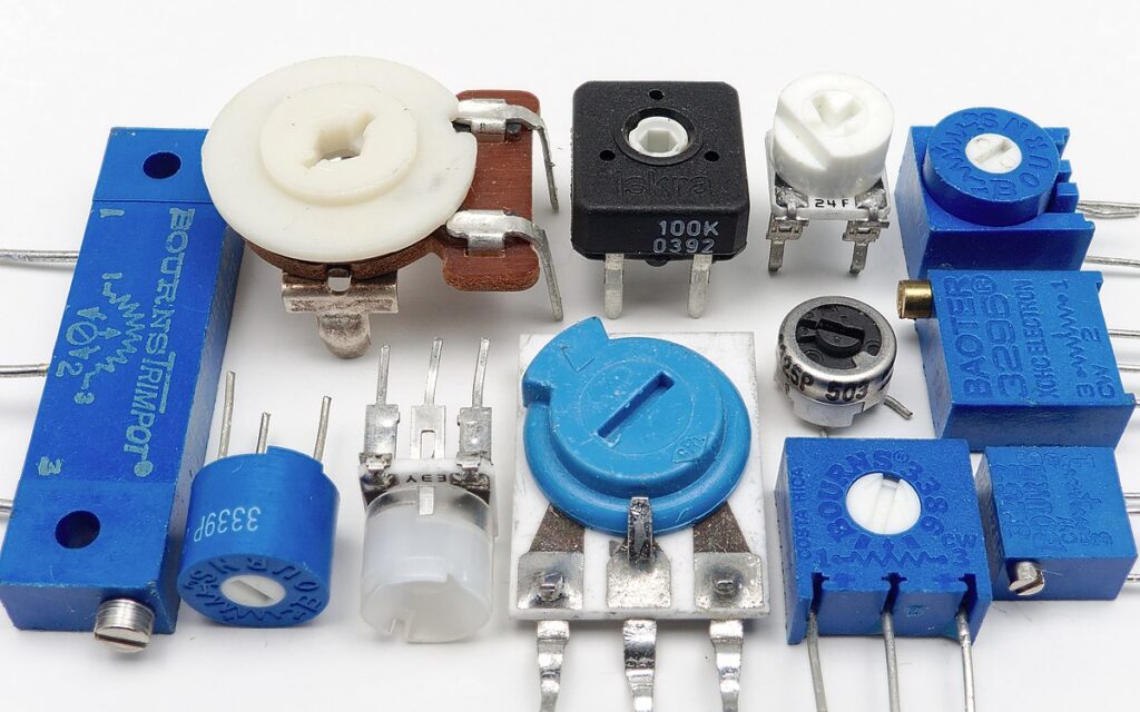
Selecting the right potentiometer type is crucial for your application's form factor and electrical requirements. Common configurations include:
Resistance changes linearly (directly proportionally) with the wiper position.
Resistance changes logarithmically with the wiper position, mimicking the human ear's loudness perception. Essential for volume controls in audio equipment to achieve natural-sounding volume adjustments.
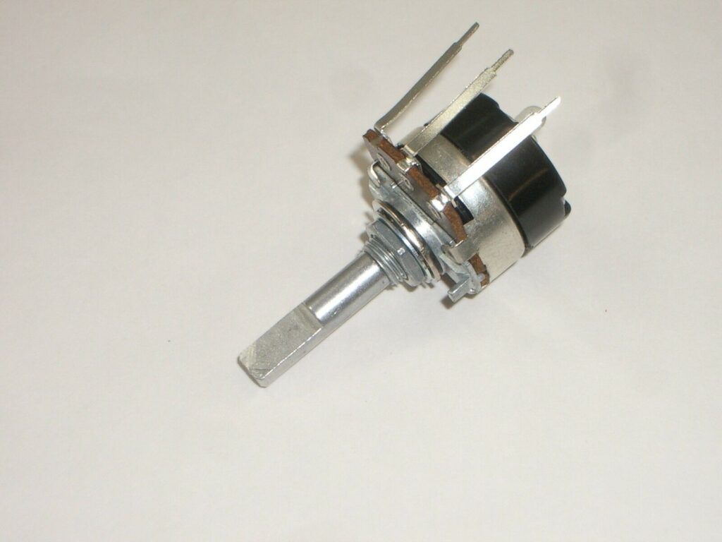
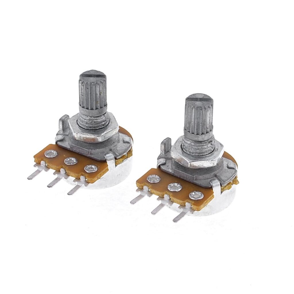
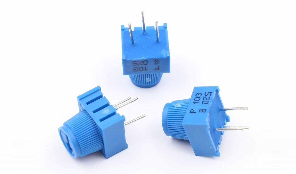
The most common type, featuring a rotating shaft to move the wiper. Used for volume/tone controls, panel-mounted adjustments, and parameter setting. Sub-types include single-turn and multi-turn.
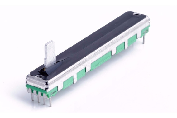
The wiper moves linearly along a straight resistive element via a sliding knob. Well-suited for graphic equalizers, studio faders, and space-constrained devices.
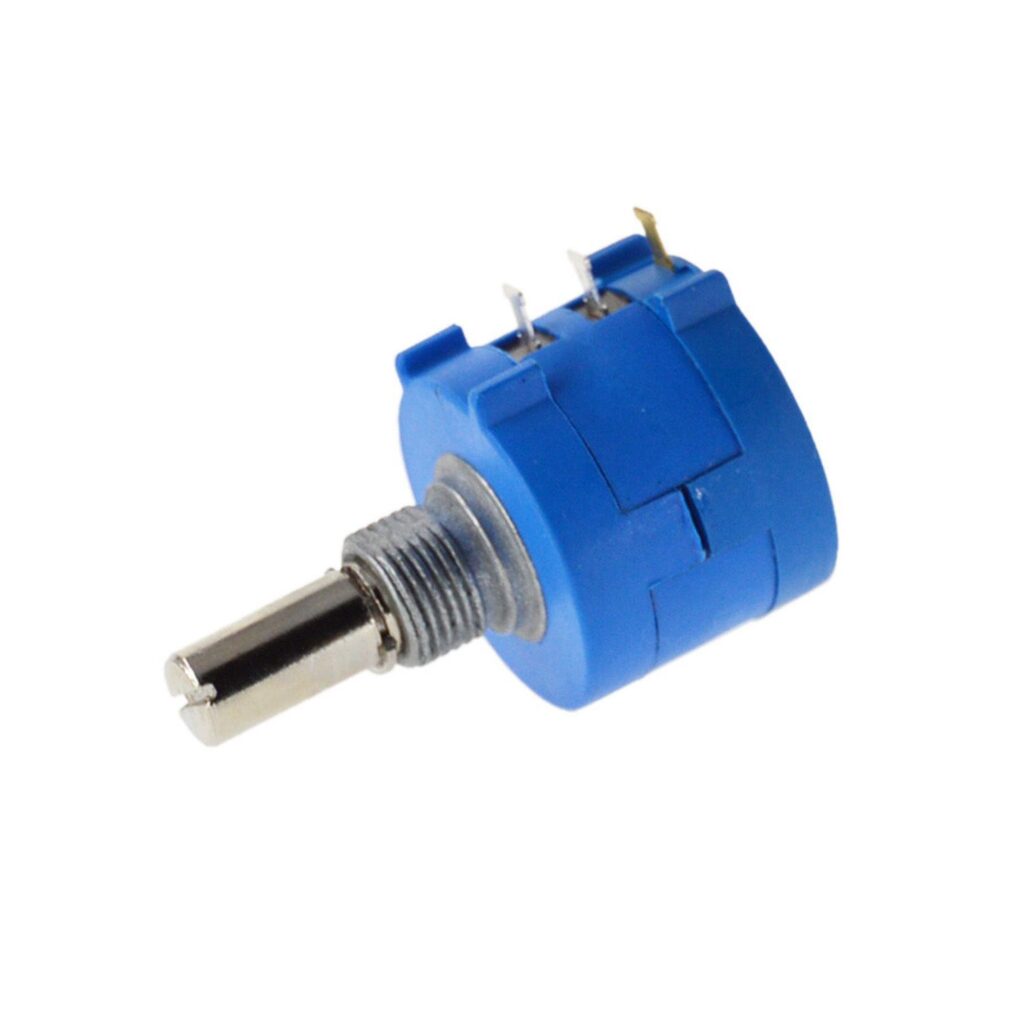
Require multiple rotations (3, 5, 10, or 25 turns) of the shaft to traverse the full resistive element. Provide extremely precise resistance adjustment and calibration, vital for instrumentation and critical analog settings.
Also known as trim pots or preset potentiometers. Small, panel or PCB-mounted pots intended for "set-and-forget" calibration during manufacturing or servicing. Adjusted with a small screwdriver.
Use digital signals (e.g., SPI, I2C) to control resistance electronically, replacing mechanical wipers. Enable remote control, automation, and precise, repeatable digital adjustments. As smart devices scale, digipots are increasingly replacing mechanical trimmers to lower BOM costs and automate calibration during the turnkey PCB testing phase.
Selecting the optimal pot goes beyond just picking a resistance value. Hardware engineers must evaluate electrical, mechanical, and manufacturing constraints:
Must be compatible with circuit requirements. Ranges span from 10Ω to several MΩ. Incorrect values affect current & voltage ranges. Pro tip: Stick to standard EIA decade values (1k, 10k, 100k) whenever possible. Contract manufacturers usually hold these in stock, reducing lead times for quick turn PCB projects.
Expressed as a percentage (±x%), indicates the accuracy of the nominal resistance value. Use lower tolerance pots (e.g., ±5% or ±10%) where precision matters. Standard consumer parts often sit at ±20%.
The maximum sustained power (I2R or V2/R) the pot can dissipate without overheating. Critical: Ensure circuit current/voltage stresses fall well within the pot's rating. Always derate the component by at least 30% for reliability. A 0.5W pot is common for general electronics.
Linear Vs. Logarithmic. Choose based on the required control response: linear for position/speed/output voltage control, logarithmic for volume. Audio controls almost exclusively require log taper.
Must fit the enclosure and PCB/front panel layout. Consider shaft diameter, length, and knob style (knurled, D-shaft, slotted).
PCB mount (through-hole or SMD), Panel mount (bushing/nut), or Stand-off mount. SMD potentiometers are cheaper to assemble on automated pick-and-place lines, but through-hole variants offer vastly superior mechanical strength against physical user interaction.
Consider dust/water sealing (IP rating), temperature range, vibration, and reliability requirements. If deploying in harsh environments, specify Conformal Coating Services during PCBA assembly, but ensure the coating process masks the mechanical moving parts of the potentiometer.
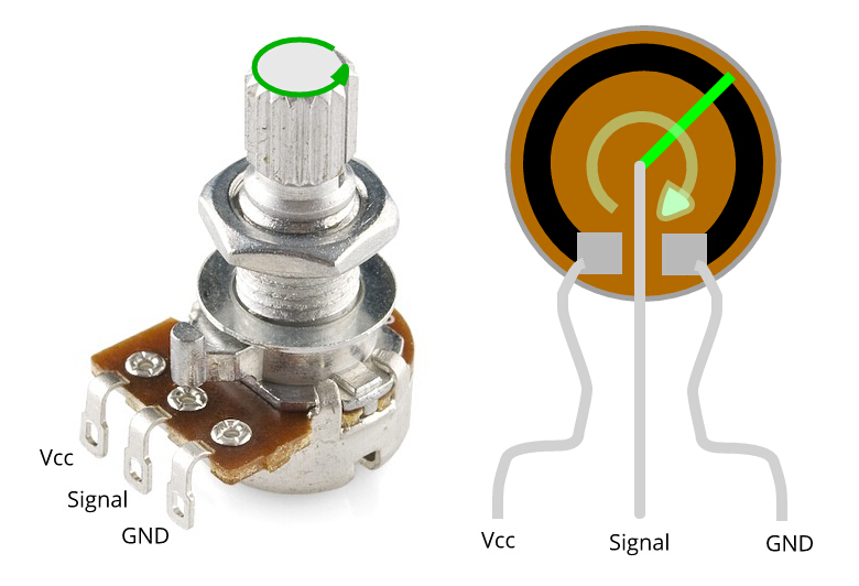
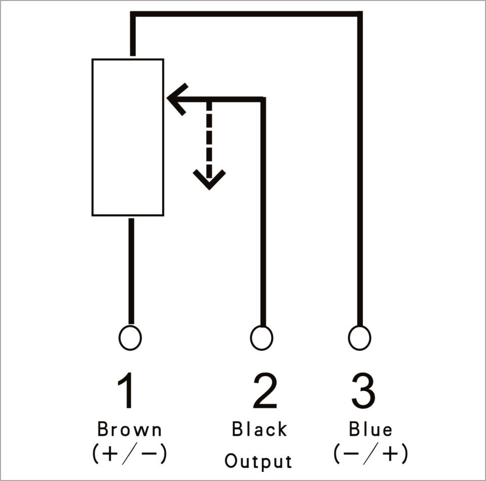
Potentiometers are commonly used in electronic circuits for controlling voltage (as a voltage divider) or current flow (as a rheostat). The standard pinout for a rotary pot looking at the shaft with pins down is: Pin 1 (Counter-Clockwise End), Pin 2 (Wiper/Output), and Pin 3 (Clockwise End).
When used to output a specific voltage based on position, you wire it as a voltage divider:
Here is an example diagram illustrating this concept.
A logarithmic potentiometer follows an exponential pattern. To wire up this type of device for audio volume control:
If you only need to change resistance (limiting current, such as tuning an LED's brightness), wire the device as a two-terminal variable resistor (rheostat):
When a potentiometer circuit fails, the root cause is usually split between wiring errors and PCB assembly defects. Here are common problems and fixes:
Always: Power down the circuit before wiring or testing with a multimeter. Double-check schematics before powering up.
Enhance performance in demanding, high-reliability applications:
Prototyping Tip: Validate advanced analog configurations with NextPCB's Quick-Turn Proto PCB Service to ensure your layout supports the potentiometer's precision.
To use a potentiometer as a simple variable resistor, connect your circuit to the center terminal (wiper) and one of the outer terminals. For best engineering practice, short the unused outer terminal to the center wiper. This prevents the circuit from breaking entirely if the mechanical wiper momentarily loses contact with the resistive track.
Technically, a mechanical potentiometer has no fixed polarity. However, standard convention dictates that when looking at the front of a rotary knob with the pins facing down, the left pin (Pin 1) is connected to ground, the right pin (Pin 3) connects to the voltage source, and the middle pin (Pin 2) is the output wiper. This ensures that turning the knob clockwise increases the output voltage.
Yes. Surface Mount Device (SMD) potentiometers are typically cheaper and faster to assemble because they utilize automated pick-and-place machines. Through-hole potentiometers require wave soldering or manual soldering, which can incrementally increase assembly time and cost. However, through-hole components offer much better mechanical stability for parts that users will interact with frequently.
A crackling or "scratchy" audio pot is usually caused by dust, oxidation, or flux residue trapped inside the component. You can clean it by spraying a specialized electronic contact cleaner (like DeoxIT) into the housing gap and rotating the knob vigorously. To prevent this at the design stage, use high-quality sealed potentiometers and ensure your circuit utilizes a coupling capacitor to keep DC voltage off the potentiometer's audio track.
Wiring done? Get your prototype assembled → NextPCB Quick-Turn PCBA
Potentiometers are fundamental components offering versatile control in countless electronic designs. Understanding their physical types, electrical selection criteria, and mastering proper schematic wiring is non-negotiable for achieving reliable hardware performance. By applying proper voltage divider principles, specifying the correct footprints, accounting for PCBA cleaning processes, and considering advanced techniques like signal buffering, you ensure your circuits function flawlessly from prototype to mass production.
Whether you're developing high-fidelity audio gear, calibrating industrial instrumentation, or designing consumer interfaces, robust potentiometer integration underpins hardware success.
| Hardware Service | Direct Link |
|---|---|
| Rapid PCB Fabrication | Get a Quick-Turn PCB Quote |
| Turnkey Component Sourcing | Upload BOM for Sourcing |
| Design for Manufacturing (DFM) | Free PCB Design Analysis Tool |
Still, need help? Contact Us: support@nextpcb.com
Need a PCB or PCBA quote? Quote now


 Surface

