Support Team
Feedback:
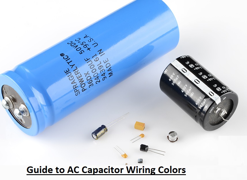
support@nextpcb.comCapacitors are passive components that have features to store electrical energy in the form of an electrical field. This feature makes it useful for different circuits. It has two conductive plates that are separated with insulated material between plates called dielectric materials. The conductive plates of capacitors are made of metallic material, and voltage is given to the plates, and they get charged. Here we will cover the details of AC capacitor wiring colors.
The AC capacitor is a very important component of the HVAC system since it controls the HVAC operation. If there is a faulty AC capacitor, there is a need to change it. Malfunctioning AC capacitors provide cool air. It can cause high power consumption, damage to the AC unit, and AC freezing. The physical structure of the capacitor and its operation are like those of a battery, but they are not batteries. The connection of capacitors is made with writing in the AC conditioning system. The AC capacitor comes with a high voltage and is dangerous. If it is not accurately handled by touch, a mistake can cause serious damage. The capacitor is an electrical component in an AC unit. It provides a motor with an additional power boost to start and work accurately. On the base of the HVAC motor, the quantity of capacitors is different. Most HVAC systems come with one inducer motor and another connected to a fan motor. One capacitor is used for the compressor motor and condenser fan motor, or two separate capacitors are also used.
The capacitor symbol and battery look the same, and their operations can also be compared. The capacitor and battery both store energy. The capacitor releases energy very quickly—about a few seconds—while the battery releases energy over time. High-speed energy releases help the motor fulfill its energy needs for starting. In the AC unit and HVAC system, the main use of AC capacitors is to deliver motors that need additional current during starting conditions. The capacitors provide additional energy, get recharged, and then again boost electricity if needed. Based on the HVAC system, there can be a need for an AC starter capacitor, an AC dural capacitor, or an AC run capacitor.
Electrolytic Capacitor
This capacitor comes with polarity and has positive and negative signs. It is used to make DC volts smooth after the voltage rectification process. It helped to decrease the ripples from the DC source. The larger capacitance of the capacitor will provide less ripple. It is used in simple linear power sources with step-down transformers.
Ceramic Capacitors
These capacitors are used as bypass capacitors for bypassing high-frequency circuits. They are connected in a parallel combination of DC power intake and ICs to bypass certain values of frequency noise in circuits that can have a bad effect on circuits. Power supplies without transformers are commonly used since they have good efficiency and small space. Surface-mount capacitors can be used in multilayer PCB boards.
Safety Capacitors
These capacitors are commonly used in inverter control circuits in AC units. They can be defined as X or Y types and used in the main part of circuits. During their handling, be careful since a charge on this capacitor can cause shock when power is cut off. Make sure accurate certifications like VED, UL, or CE markings exist on the structure of the capacitor before connecting them in circuits. This capacitor with inductor coils is used to decrease the harmonics that are produced due to the fast switching of the AC power source through the IGBT.
Start and run AC capacitors.
These capacitors are used in single-phase electric motors. The start capacitor is used for shifting the phase difference between the starting and running windings of the capacitor start motor. This difference resulted in starting torque, which is used to start the motor with the full load connected.
The run AC capacitor used for shifting the phase difference between windings causes high starting torque to be produced. The marking on the single-phase compressor finds connections in the motor. The labels are R used for running the winding connection, S for starting the winding connection, and C used for the common of two windings.
The AC capacitor wiring colors are normally based on convention; the color of the wiring means certain terminals have a function when making connections. It must be noted that each manufacturer has different colors of wires for different functions.
Normally used color codes for AC capacitor terminals are listed here.
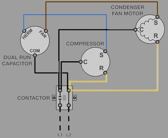
There are different parts of an AC capacitor, and it is not easy to find the operation of an electrical circuit. The AC capacitor wiring color diagram defines all terminals in the capacitor with their wiring connection with a capacitor to the motor of the fan, compressor, power source, and connected load. The color code of the wires in the diagram is related to the color code of the wires on real capacitors. For example, black wire is used to show the common terminal, FAN is used to show the brown wire, and the red wire is shown with HERM. This diagram is also used to show the connection of connected components of a circuit, like a relay, control board, etc. The connection is denoted by simple lines connecting one component to another. It is important to note that some different manufacturers and countries use different colors for different terminals, so before using a capacitor in the circuit, read the color coding for each terminal. If an accurate connection is not made, it can affect the device and circuit.
The wiring of a dual-run capacitor is different from that of an AC unit, so follow these points to make a connection to the dual-capacitor wiring.
The AC capacitor is monitored with the use of a multimeter and terminals that make connections. The multimeter is a device that is used for measuring electrical parameters. An AC capacitor's capacitance is measured in microfarads. Some other techniques are used to test AC capacitors. One technique is when the circuit is in a state, and another is when the circuit is off. Any method used to test must be done professionally since when the capacitor is separated from the circuit, the electrical charge has a high value.
For testing, the separated AC capacitor multimeter must be set to a microfarad value. Then the capacitor must be checked between the common and other points. Based on the capacitor, it has different terminals. The measured reading between the C pin and other pins of capacitors is measured in microfarads. During the checking of the capacitor, if the circuit is operating, there is a mathematical expression used to test the ampere of the motor. Multiply by 2652 and divide by the voltage rating of the common and other terminal values that are tested.
Microfarad rating = (AMPS / 2,652) * Voltage
Every capacitor comes with the microfarad rating mentioned, which defines the accurate function of the capacitor. Most capacitors are operated with five to ten percent of the mentioned microfarad rating. If a capacitor is tested and has a result value not in the five- to ten-percent range, it must be replaced.
The fan capacitor must be connected during the motor installation. It is best to note the details of wire colors and connections.
The start or run capacitor can be linked to one capacitor, called a dual capacitor with 3 pins, but can be split between two different capacitors. The start capacitor gives the fan motor torque that is needed to start spinning and stop when the run capacitor is on, and it also provides the motor with additional torque if required. If start capacitors are affected, the motor will not be turned on. If the capacitor is bad, then the motor will get on, but the operating amp will be larger than normal, resulting in the motor overheating and reducing its operating life. When the condensation fan motor is replaced, a new start run capacitor must be connected.
Proper maintenance and replacement of faulty capacitors at the proper time is best for the effective operation of the HVAC system. Following the safety measures, accurately finding the capacitor problems, and following accurate wiring techniques help to make reliable HVAC. So it is preferred that you get the services of an HVAC expert to make sure of accurate capacitor connections and wiring with the system. The AC capacitor's color code wiring is according to standard, with the color of the wiring defining the operation of the terminal that is connected. It is important to check the wiring diagram of certain devices to make sure the wire connection is correct since if the wiring is not correct, it can damage the system. The AC capacitor wiring color details are referenced according to the standard color code used for the wiring of the capacitor and the operation of the terminal where they are connected. It does not have data on the connection between different pins of capacitors and other components.
- How to Discharge a Capacitor: Comprehensive Guide
- 12 Commonly Used Components on PCBs for Beginners
- Free Worldwide Shipping on Over 600,000 Electronics Components with HQ Online
- Free PCB Assembly Offer is Now Live: Experience Reliable PCB Assembly from HQ NextPCB
- HQ NextPCB Introduces New PCB Gerber Viewer: HQDFM Online Lite Edition
Still, need help? Contact Us: support@nextpcb.com
Need a PCB or PCBA quote? Quote now
|
Dimensions: (mm) |
|
|
Quantity: (pcs) |
|
|
Layers: |
Thickness: |
|
|
|