Support Team
Feedback:
support@nextpcb.comIntroduction
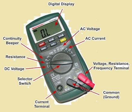
The multimeter is an electrical device used in electronic projects and electrical systems to measure the different electrical parameters. With the use of this meter, anyone has to get the required valve of electrical systems. The function of this meter is based on the Ohm Law which is a combination of voltage, current, and resistance. In this post, we will cover the basics of this meter and will discuss its different functions and proper function understanding. So let's get started!
The multimeter is considered the main part of the electrical system. It is a known versatile device due to having features to measure different electrical through a single unit so preferred by any engineer or electronic student. There are two main types of multimeter first the digital multimeter and second the analog multimeter. A digital multimeter comes with a digital display that makes it to easy read and offers correct electrical values. While in an analog meter, there is a need for a connected dial to provide the measured values. Due to easy use and high accuracy, digital multimeters are used, but analog multimeters are used for variation in measurements.
The main function of the multimeter is to measure voltage. it can used to measure both AC and DC voltage. To measure volts meter is connected to the circuit by making the connection of its red and black probes that are positive and negative. So to get accurate values and follow the safety measures during the use of meter are important.
DC voltage measurement is a very common value measured from a multimeter. The DC voltage calculation feature of the meter is used to find the value of the electrical potential difference between two points in the circuit where the DC current is flowing. Potential difference is measured in volts. For measuring the DC voltage set the DC V mode on the meter. Then connect the negative terminal of the circuit with the INPUT LO connection of the meter and the positive part of the circuit with the INPUT HI of the meter, then on the supply connected with the circuit results current flow is measured in the circuit on the meter.
The process of measuring the AC volts on a meter is the same as the DC volts measured. However, the difference is that a measuring alternating current, AC mode of the meter is used to connect with the circuit. AC voltage is also measured in Volt units. Before measuring ac voltage set the meter at AC V mode and connect probes. Connect the positive terminal of the circuit with INPUT HI and the negative terminal to INPUT LO. Then the power supply current flowing through the circuit will provide the voltage of the circuit on the meter
There are different methods used to measure the resistance of the circuit through the use of a multimeter based on the accuracy required in measured values. Multiemer finds the value of circuit resistance by providing the small value of current in a circuit and then calculates the value of voltage loss in the circuit. The current given to the circuit is known so voltage loss measured in the circuit is used to measure the value of resistance with the use of OHM law that is V= IR. When the circuit is connected to the meter the probe wires also have some resistance that is added to the circuit's measured resistance and made different to find the accurate value of resistance. So there are two other techniques used to measure the accurate resistance
If you need highly accurate resistance measurement. Then use 4 wire resistance measurement configuration. There are two extra probes used for this configuration, so it is known as 4 wire. Two probes are used to give current to the circuit and the other two measure voltage in the circuit. This process avoids the high value of voltage losses due to probe wire resistance, as it provides the accurate voltage value and resistance measured.
For making a 4-wire resistance arrangement with the use of a benchtop meter choose the ohm mode on the meter and press this button more than one time to arrange a four-wire mode. Connect the first two probes with INPUT high and INPUT LO and the other two with SENSE HI and SENSE Low ports of the meter. Make sure the circuit is in the off state and then probe the required part of the circuit with the use of HI probes on a positive part of the circuit and LO probes on the negative part of the circuit.
DC current measurement is helpful to find the single direction flow of current in the circuit its measuring unit is ampere. To measure the current in the circuit it must be open and then connected with a meter to measure the current. This arrangement helps the current flow in the meter. For measuring the current meter connected in series combination of resistance and voltage is measured with the parallel configuration of the meter with the circuit.
If you are measuring DC current with the use of a benchtop meter choose I DC mode on the meter. Make the connection of the positive probe of the circuit with the mA port of the meter to measure the small value of the current and use the 10A port for measuring the high current in the circuit. Attach negative probe with INPUT LO port. After making the right connection supply the circuit and measure the value of the DC.
AC current is measured in an AC system that continuously varies the directions. its measuring unit is ampere. As we measured DC through the series connection of the meter in the circuit AC also connects the meter in the circuit in a series combination. To measure the AC current set I AC mode of mete and make the connection of the positive part of a circuit with the mA port of the meter to measure the small value of current and for high current use 10A port. Connect the negative probe with the INPUT LO port then supply the circuit and measure the value of ac curent. Try to avoid common mistakes normally new learners use mA for measuring larger current values that will affect the meter working so for measuring 200mA current use the 10A port to affect the fuse connected in the meter.
The multimer can be used to measure diode losses in forward-biased conditions of the diode. In the forward biasing state positive leads of the source connect with the anode of the diode and negative with the cathode of the diode. To find the value of the diode voltage losses meter gives the same value of voltage across the probes and increases voltage values till there is an electrical connection between two probes. Diode voltage losses are measured in DC volts.
For measuring the diode losses set the diode test mode of the meter by pressing the button that has the diode symbol. Attach the positive probe with the INPUT HI port and the negative probes with the INPUT LO port. Make sure the circuit is not connected to the power supply. Now connect the power supply with the diode according to the required polarity measures voltage losses
With the use of a multimeter, we can measure the frequency of the AC signal. Frequency is a measurement of cycles repeated in one second. If the sine wave is repeated 20 times in one second will have a twenty-hertz frequency. Input frequency on the meter can change so before measuring a high value of frequency check that the meter can measure the frequency value. Similar to voltage we frequency measured in parallel configuration of the circuit.
To find the value of high frequency with high accuracy use the dedicated frequency counter. To measure the frequency with the meter set the meter to FREQ mode then attach the opposite probe with the INPUT HI port and the negative probe with the INPUT LO port. Make sure the supply is connected with the circuit where the frequency is measured.
|
|
|
|
|
|
|
|
|
|
|
|
|
|
|
|
|
|
|
|
|
|
|
|
|
|
|
|
|
|
Set Multimeter:
Set Range:
Remove Resistor:
Connect the Probes:
Read the Display:
The value resistance is measured through a digital multimeter by sending a small known voltage through the resistor and then measuring the required current. Here process explained
The multimeter is a very important device in the electronic field to measure different parameters of a system like resistance, voltage, and current. With the use of this meter, we can measure AC, DC voltage, AC, DC and it is used for diode testing and can find the value of frequency. Now it has become very common in our system and every engineer must have a proper understanding to find different values of electrical system parameters.
- What is the Difference between an Analog Multimeter and a Digital Multimeter?
- What’s The Difference Between Watts And Volt-Amperes?
- Free PCB Assembly Offer is Now Live: Experience Reliable PCB Assembly from HQ NextPCB
- HQ NextPCB Introduces New PCB Gerber Viewer: HQDFM Online Lite Edition
Still, need help? Contact Us: support@nextpcb.com
Need a PCB or PCBA quote? Quote now
|
Dimensions: (mm) |
|
|
Quantity: (pcs) |
|
|
Layers: |
Thickness: |
|
|
|