
Support Team
Feedback:
support@nextpcb.comIn the domain of electrical and electronic engineering, the symbols of the electronic and the electrical components are the main thing that drives the domain because all of the designs are based on the symbols of the components.
If you are a beginner in this domain. First, you have to understand the symbols are using for the designing of the PCBs. Once you are good at electronic and electrical symbols, you will gain the potential to understand the concept of PCBs by analyzing the PCB diagram.
Because of that, the electronic and electrical communities in the world got together to use a standard set of symbols for every component.
In this article,
A visual depiction of electrical and electronic components is an electrical symbol. These symbols enable us to identify a specific electronic component in a circuit. Electrical symbols use national and international standards for definition. The components of electrical and electronic circuits solely show with the use of circuit symbols, which do not specify their purpose or method.
Circuit symbols use for the representation of each component in a circuit. Each component has a particular number of connections or pins. The circuit schematic includes labeling for the pins and connections. Each sign also has a distinctive quality that distinguishes that particular component.
One of the most fundamental parts of an electrical circuit diagram is an electric cell. A positive and a negative terminal are present. A battery can create by fusing many cells. A single-cell diagram and the diagrammatic depiction of a battery are extremely similar. The wires help for connecting the components in the circuits. The wires at the connecting sites are shown as blobs.
A circuit diagram includes several parts, including switches, capacitors, and resistors. Circuits also use LEDs and battery cells in addition to resistors and capacitors. Nets or trails are used for linking them. Each element has a unique symbol and characteristics. A resistor, for instance, marks with its size, voltage rating, and wattage symbol. Other parts will have symbols for their size and wattage, including LEDs and batteries.
The definition of an electronic circuit is a grouping of different electronic parts that permit the movement of an electric current. To create a circuit diagram, the electrical components have two or more terminals that can use for the joining of one component to another. A system can create by soldering electronic components on circuit boards.
The ground electrode, battery, and resistor are fundamental electrical and electronic symbols. You may make an electrical diagram that is more precise and easier to comprehend by being aware of them. These symbols can use to illustrate circuits with more complexity. A capacitor and a resistor, for instance, may include in a battery. Anyone will be able to draw an electrical diagram using these fundamental symbols.
When building circuits for a project or creating a PCB for a project, understanding electronic symbols is crucial. It is challenging to develop a project if we don't understand the symbols used in the schematic circuit.
Let's go deeper into symbols:
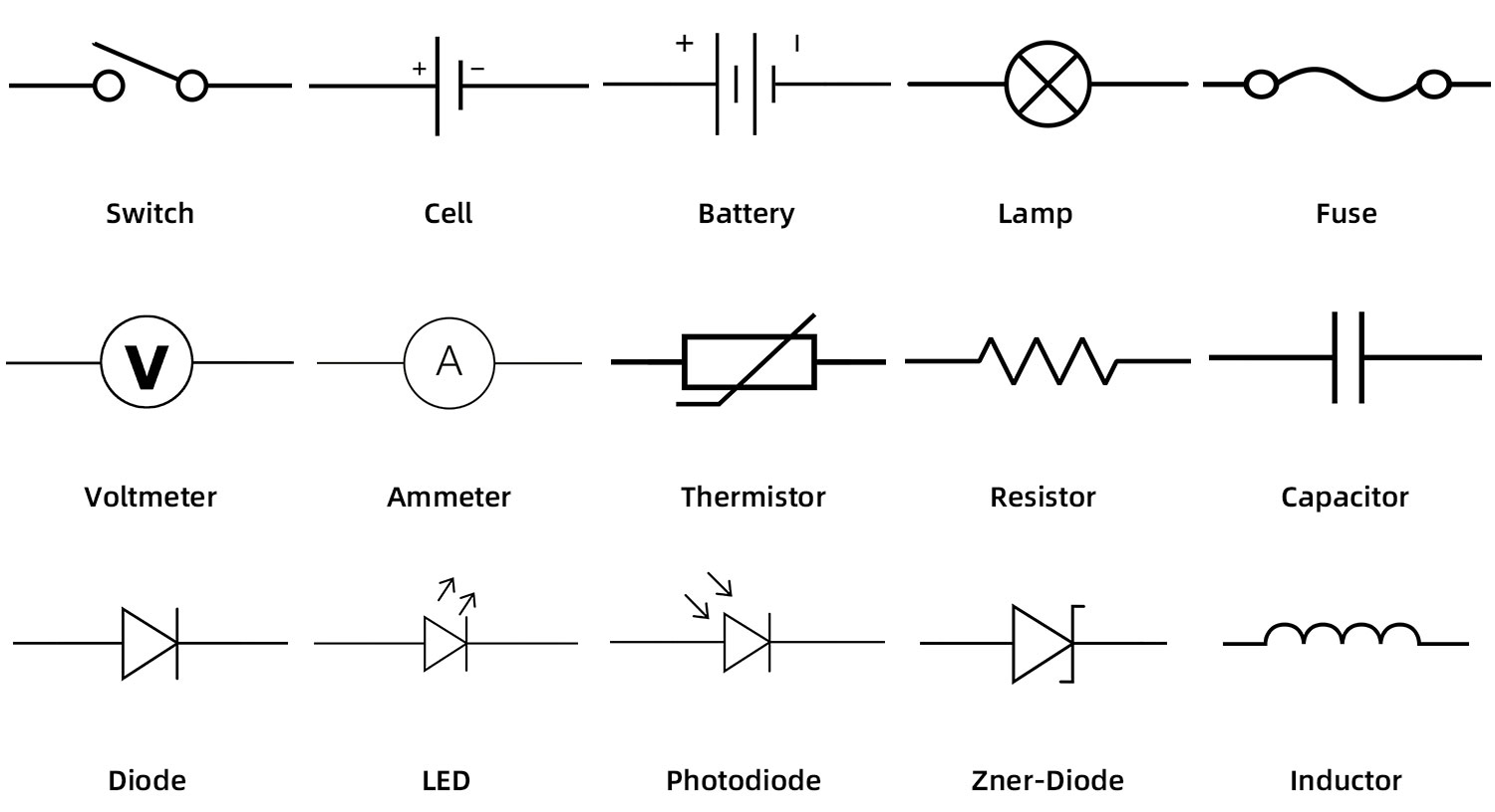
Circuit diagrams are used to portray the symbols used in electronic circuits virtually. Every circuit uses standardized symbols to represent the various parts. To represent fundamental electrical devices, several electronic circuit symbols are employed. Electronic circuit components such as switches, wires, sources, ground, resistors, capacitors, diodes, inductors, logic gates, transistors, amplifiers, transformers, antennas, etc., are typically represented by circuit symbols. Circuit diagrams employ these electrical and electronic circuit symbols to show how a circuit functions.
Electronic circuit symbols are signs, drawings, or pictograms used to represent various components in an electronic circuit's schematic diagram. Due to some universal standards established by ANSI & IEC to represent the components, symbols vary depending on the country.
Wires, power sources, resistors, capacitors, diodes, transistors, meters, switches, sensors, logic gates, audio equipment, and other components mostly illustrate by the symbols which are for electronic circuits. Additionally, the majority of electrical circuit symbols include switches, cells, batteries, etc.
Electrical and circuit diagrams both utilize symbols to indicate a component. Another name for it is a schematic symbol.
According to its operating features, each component has a typical functionality. A connected route connects electronic components in an electronic circuit or schematic layout to complete the circuit. The corresponding symbols for it serve to symbolize these components. Most of the symbol designs are based on different national and international standards. Instances include IEC standards, JIC standards, ANSI standards, IEEE standards, etc. Although electrical symbols are standardized, they might differ from engineering discipline to engineering field depending on previous traditions.
This makes it simple and clear for everyone to understand electrical circuits, schematic diagrams, and floor layouts. Unless the circuit is constructed with the components being physically used, electrical symbols only represent the individual parts of electrical and electronic circuits; they do not describe any functions or processes. There is a circuit symbol for each electrical device or component used in a circuit, such as passive components, active components, measuring devices, logic gates, etc. (For example, the circuit on a breadboard or assembled printed circuit board).
Electronic symbols primarily use for simplifying drafting and making circuit diagrams easier to understand. The whole industry uses the same symbols. A symbol's precise meaning is provided by the inclusion of a dot, line, letter, letter spacing, shading, and number. One has to be familiar with the basic structure of various symbols to comprehend circuits and their corresponding symbol meanings.
These symbols, which are represented by electronic drawings, are required for circuit design to communicate information about wiring, layouts, equipment locations, and its intricacies so that component arrangement may be done with ease.

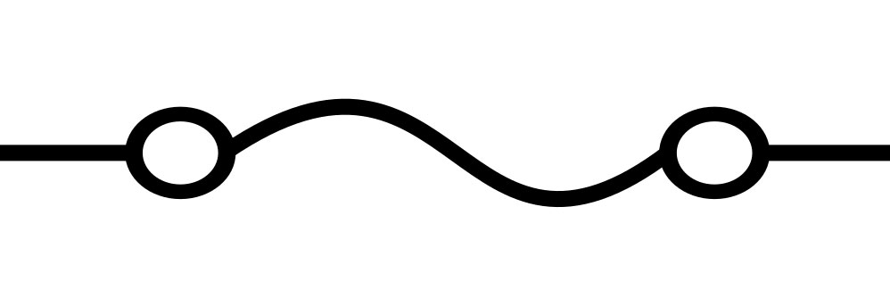
In the application, there are many types of switches. Selecting the switches depending upon the application. The main purpose of a switch is to make the circuit to the "open" condition or to the "close" condition. The following are examples of some switches commonly identifiable in the industry.
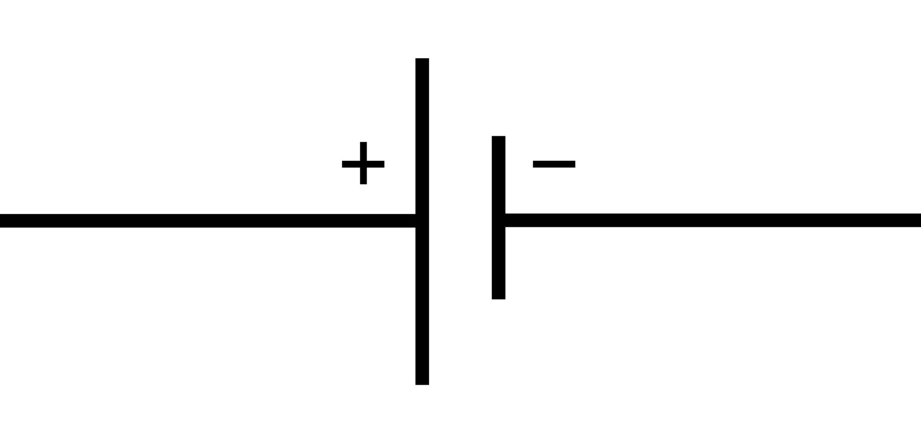
The potential difference is provided by cells, which power the circuit. This is the source that mainly develops the charge for the circuit. Here chemical energy is the base energy source that energizes the whole circuit.
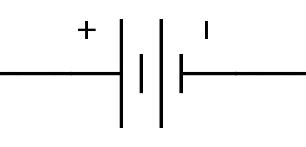
Making a connection between a few cells makes a battery. It is more energized than a single cell.
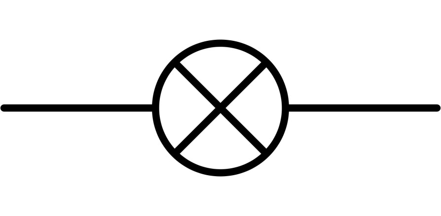
The lamp will light up when the electrical charge is flowing through this. This results from an electrical current heating a thin filament, which causes it to glow.
A safety component is a fuse. It has a lower melting-point wire in it. As a result, when the current is too high, the wire burns, breaking the circuit. By cutting the circuit, the excessive current can stop from starting fires and harming other parts.
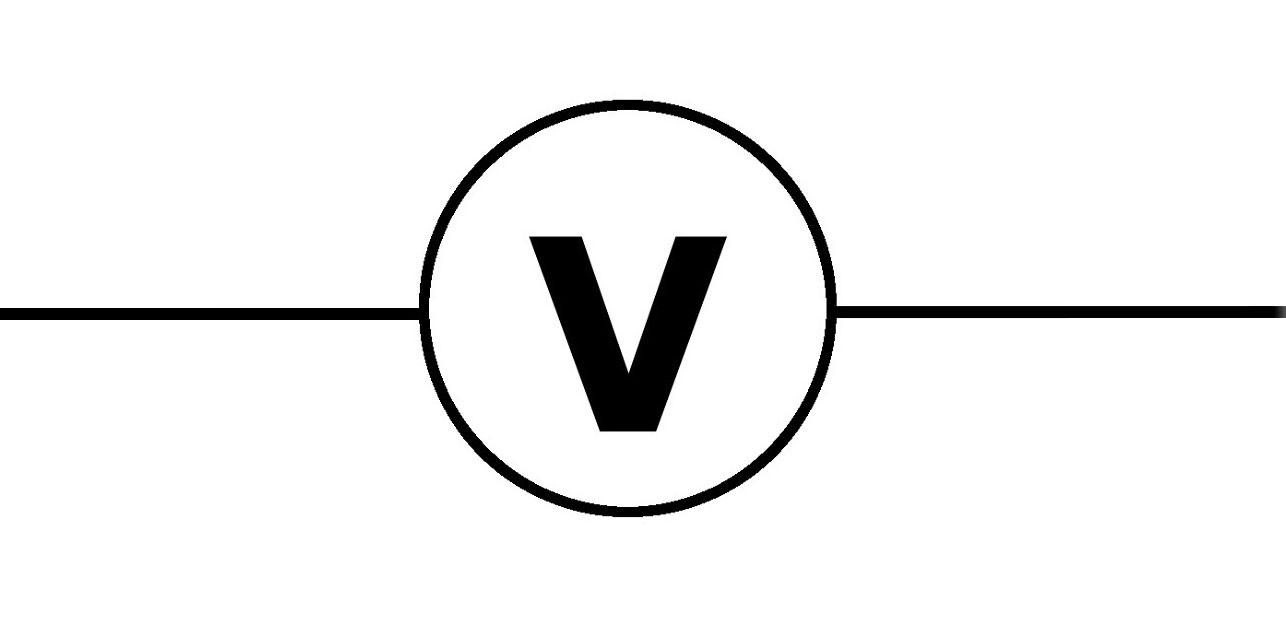
Voltmeter, an instrument that measures voltages of either direct or alternating electric current on a scale usually graduated in volts, millivolts (0.001 volts), or kilovolts (1,000 volts). Many voltmeters are digital, giving readings as numerical displays. The instruments just described can also provide readings in analog form, by moving a pointer that indicates voltage on a scale, but digital voltmeters generally have a higher order of accuracy than analog instruments. For example, a common analog voltmeter is likely to employ an electromechanical mechanism in which current flowing through turns of wire translates into a reading of voltage. Other types of voltmeters include the electrostatic voltmeter, which uses electrostatic forces and, thus, is the only voltmeter to measure voltage directly rather than by the effect of current.
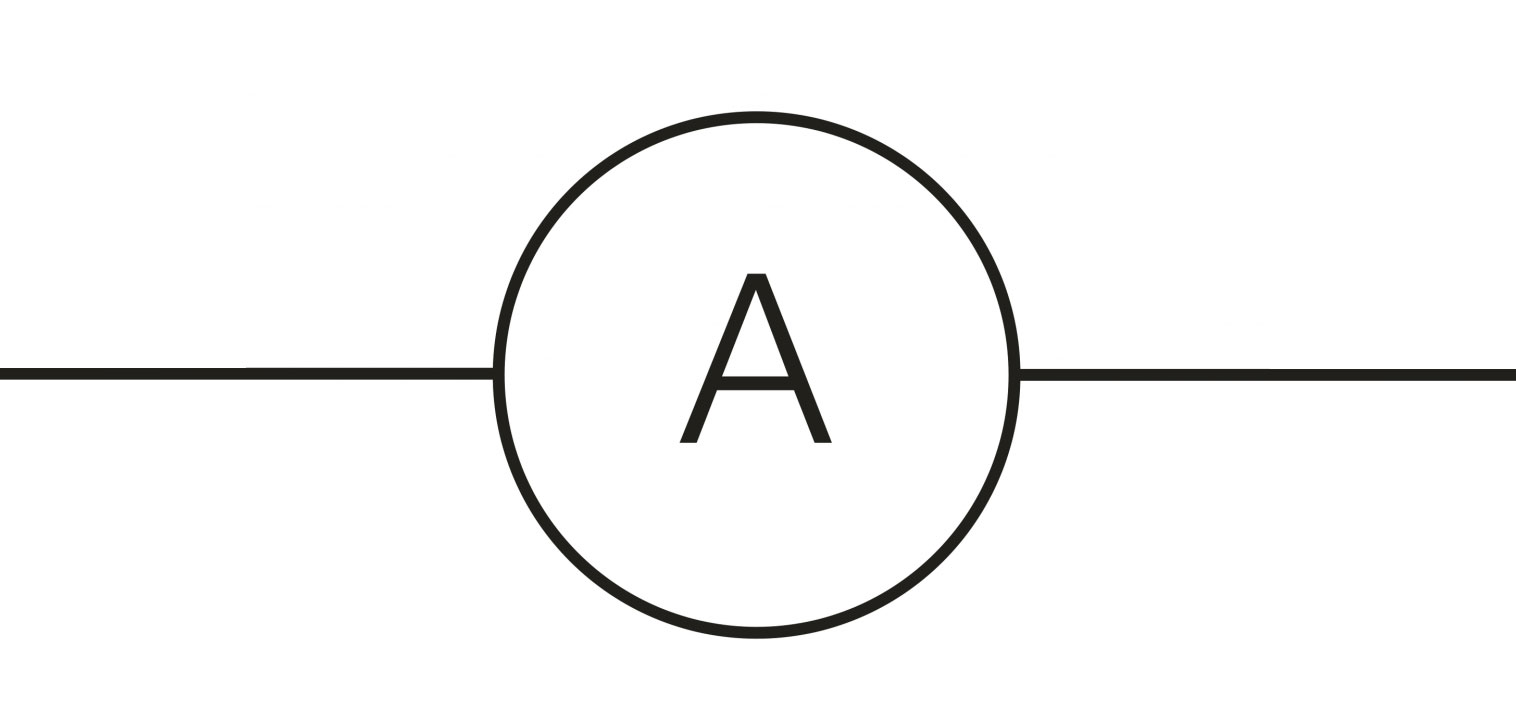
Ammeter: a device for measuring electric current in amperes, either direct (DC) or alternating (AC). Due to the fact that a shunt running parallel to the meter carries the majority of the current at high current values, the ammeter can measure a wide range of current values. A circle with a capital A inside it serves as the icon for an ammeter in circuit diagrams.
The principles of operation and accuracy of ammeters differ. Accuracy ranges from 0.1 to 2.0 percent when measuring the direct current flowing through a coil hanging between two magnets' poles using the D'Arsonval-movement ammeter.
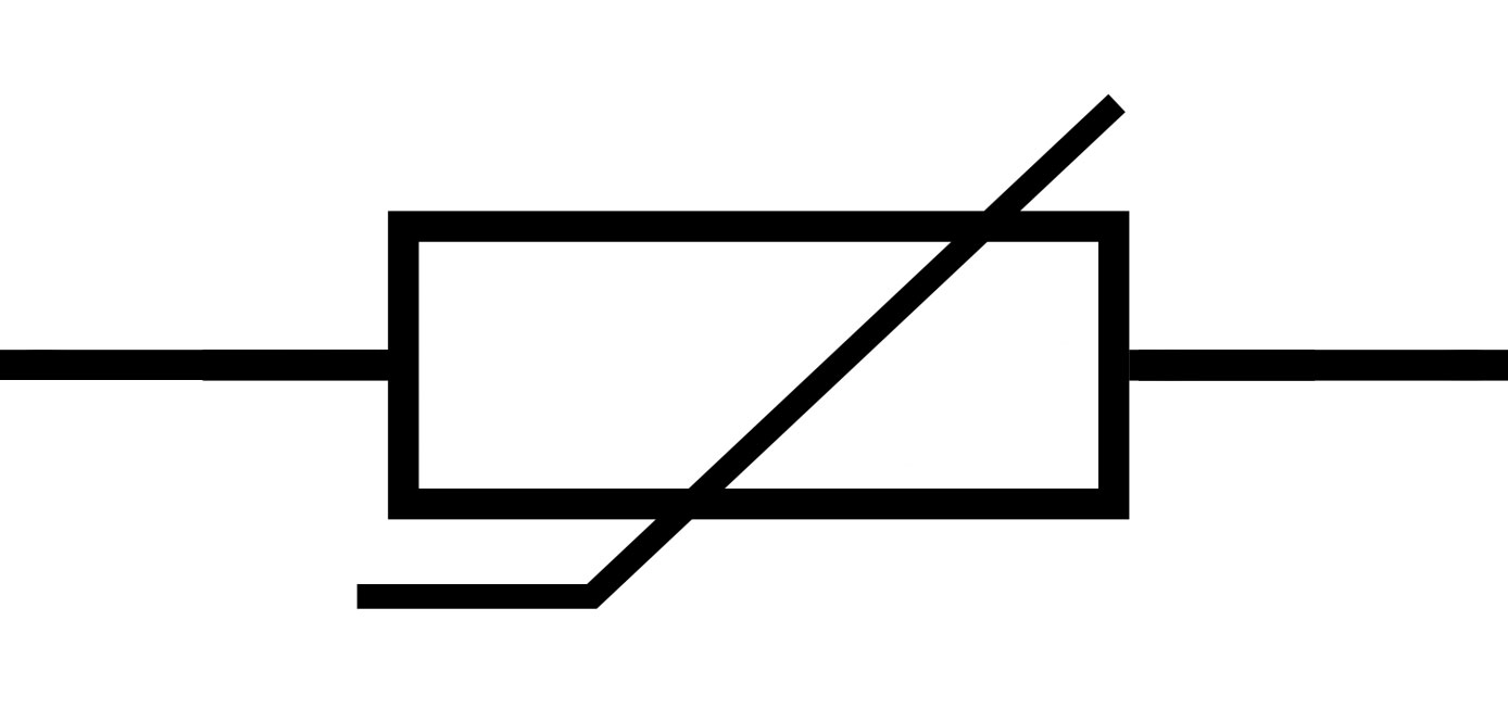
Thermistors are a specific kind of semiconductor that responds to temperature changes like a resistor; they have higher resistance than conducting materials but lower resistance than insulating materials. The electrical resistance of a thermistor can identify, and its measured value can be linked with the ambient temperature to establish a temperature measurement.
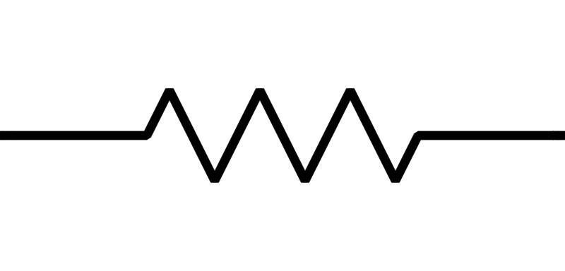
The resistor is an electrical component that is passive and adds resistance to the flow of current. They are present in practically all electronic circuits and electrical networks. Ohm is a unit of measurement for resistance. When a resistor has one volt (V) drop across its terminals and a current of one ampere (A), the resistance that results can measure using ohms. The relationship between the current and voltage at the terminal ends is linear. Ohm's law illustrates this ratio:
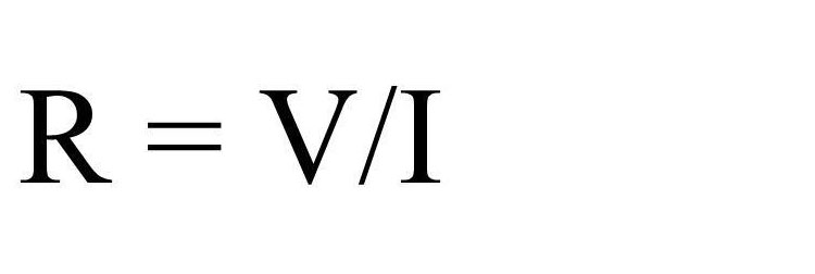
There are numerous applications for resistors. Among some examples are voltage division, heat production, matching and loading circuits, gain control, and time constant setup. They have resistance values that span more than nine orders of magnitude and use in various applications in the industry. They can be smaller than a square millimeter for electronics or utilized as electric brakes to disperse kinetic energy from moving trains.
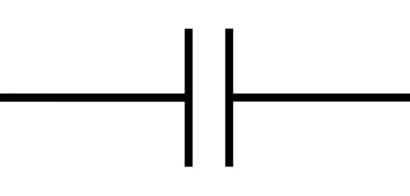
A capacitor is a method to keep the voltage constant. They can help to lessen voltage pulsation. The capacitor is charged when a high voltage is given to the parallel circuit, and it is discharged when a low voltage is used.
The letter C represents the capacitor with two terminals. A symbol resembling two parallel plates between two terminals represents the capacitor. The design employs two separate capacitor symbol kinds. A polarized capacitor uses one, whereas a non-polarized capacitor uses the other. In the polarized capacitor symbol, one of the parallel plates draws a bent line, making it distinct from the other one. The curved plate, representing the capacitor's cathode, should have a lower voltage than the anode pin (plane-parallel plate). The plane-parallel plate represents the anode of the capacitor; the plus symbol (+) denotes the anode.
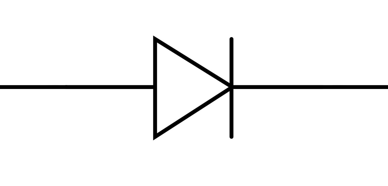
A diode is a semiconductor gadget that effectively switches current in a single direction. While significantly limiting current flow in the opposite direction, it permits easy flow in one direction.
The diode is a polarized, two-terminal device that can identify with the letter D. One terminal of a diode is positive (anode), while the other is negative (cathode). An anode is the base of a triangle, while the closed side is its cathode.
A horizontal isosceles triangle pressed up against a line connecting two terminals forms the shape of a diode. The diode operates under the forward bias situation, or we may say that the diode will let the current flow in this circumstance.
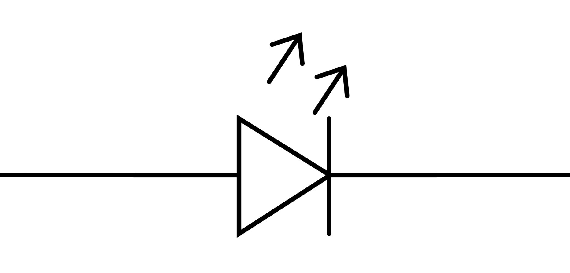
The LED symbol is also similar to the diode symbol but with extra arrows. These arrows appear to radiate out from the triangle and point in the opposite direction. Anode and cathode connections are found on polarized components like Led. LEDs (Light Emitting Diodes) transform electrical energy directly into light as opposed to traditional light sources, which first convert electrical energy into heat before turning it into the light. This results in efficient light creation with little electricity waste.
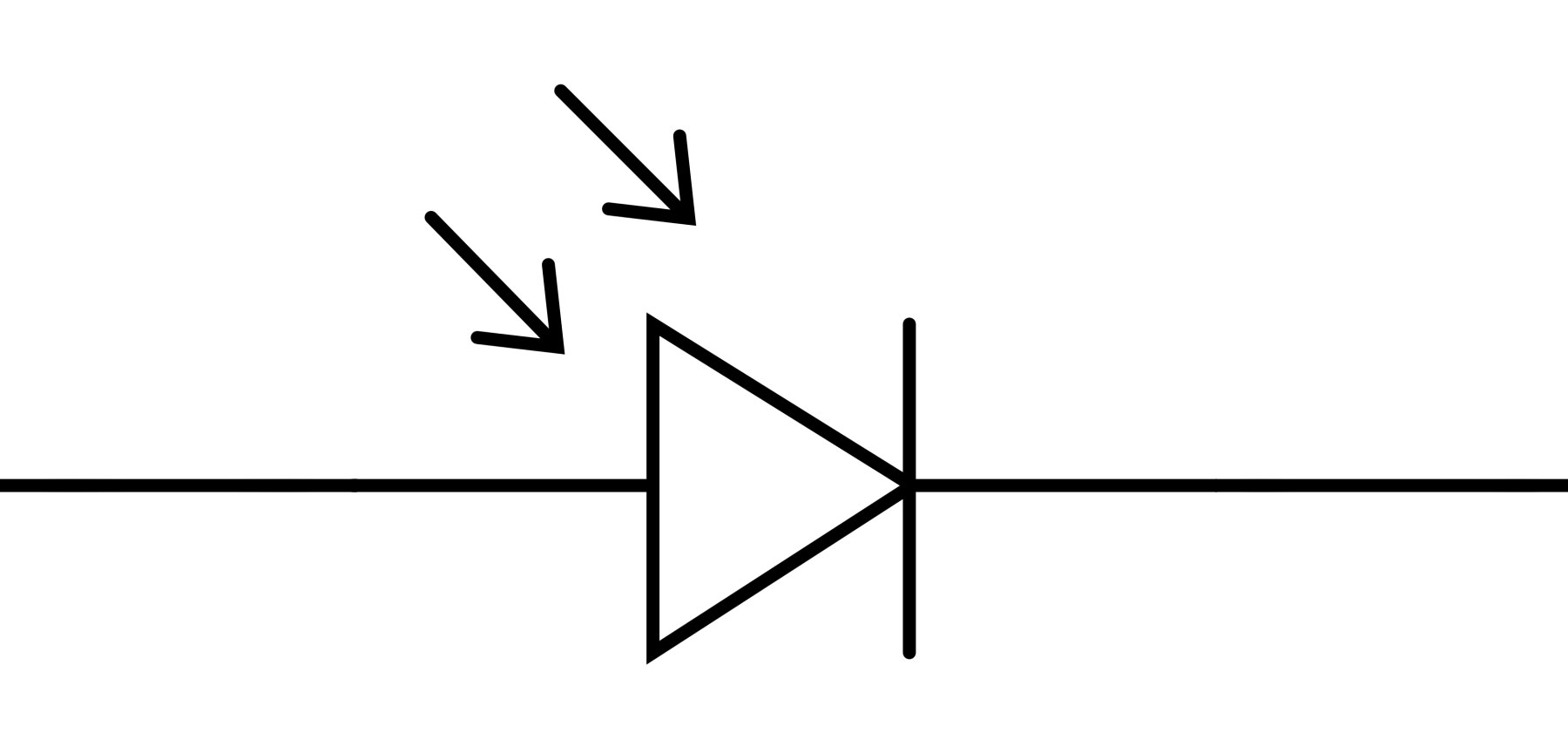
In contrast to the LED symbol, the photodiode's symbol has arrows striking the diode. As arrows that hit the diode represent photons or light. Anode and cathode are the names of the two terminals on the photodiode.
Using a photodiode, light converts into electrical current.
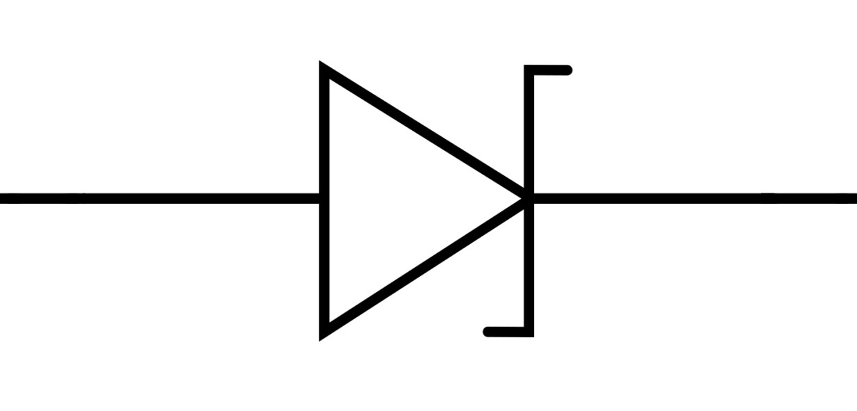
A silicon semiconductor Zener diode is a circuit component that allows current to flow either forward or backward. The diode is made up of a unique, heavily doped p-n junction, intended to conduct in the opposite way when a specific voltage is attained.
The reverse-breakdown voltage of the Zener diode is clearly defined; at this voltage, the device begins to conduct current and can continue to function continuously in the reverse-bias mode without suffering harm. In addition, the voltage drop across the diode is constant over a broad voltage range, which qualifies Zener diodes for use in voltage control.

A non-polarized two-terminal component is an inductor. Looping coils or curved bumps are visually identifiable there in between two terminals on an inductor's symbol. The international representation of an inductor is a filled-in rectangle, instead of loopy coils.
In switched-mode power systems that generate DC current, inductors are frequently employed as energy storage components. The circuit receives energy from the inductor, which stores energy, to keep the current flowing during "off" switching periods, permitting topographies where the output voltage is higher than the input voltage.
In conclusion, electronic circuit symbols are signs, drawings, or pictograms used to represent various components in an electronic circuit's schematic diagram. Due to some universal standards established by ANSI & IEC to represent the components, symbols vary depending on the country.
The circuit diagram virtually portrays circuit symbols. Every circuit uses standardized symbols to represent the various parts. To represent fundamental electrical devices, several electronic circuit symbols are the best option. Electronic circuit components such as switches, wires, sources, ground, resistors, capacitors, diodes, inductors, logic gates, transistors, amplifiers, transformers, antennas, etc., typically have separate circuit symbols. The linking of the circuits can analyze through circuit diagrams that employ these electrical and electronic circuit symbols. Wires, power sources, resistors, capacitors, diodes, transistors, meters, switches, sensors, logic gates, audio equipment, and other components are mostly represented by the symbols used in electronic circuits. Additionally, the majority of electrical circuit symbols include switches, cells, batteries, etc.
Still, need help? Contact Us: support@nextpcb.com
Need a PCB or PCBA quote? Quote now
|
Dimensions: (mm) |
|
|
Quantity: (pcs) |
|
|
Layers: |
Thickness: |
|
|
|


